
WHAT YOU’LL LEARN IN THIS GUIDE
- What a vapor recovery system is and how it differs from a flare or vapor combustor
- Which EPA regulations require vapor recovery at production sites (40 CFR 60 Subpart OOOOb)
- How to determine if your tank battery or separator needs a VRU or a combustor
- Sizing a vapor recovery unit: flash gas volumes, BTU content, and pressure
- The difference between a VRU, a vapor combustor, and a BTEX condenser system
- Hero Process Solutions’ vapor recovery product line and when each unit applies
- Common compliance mistakes at storage tank batteries that lead to permit violations
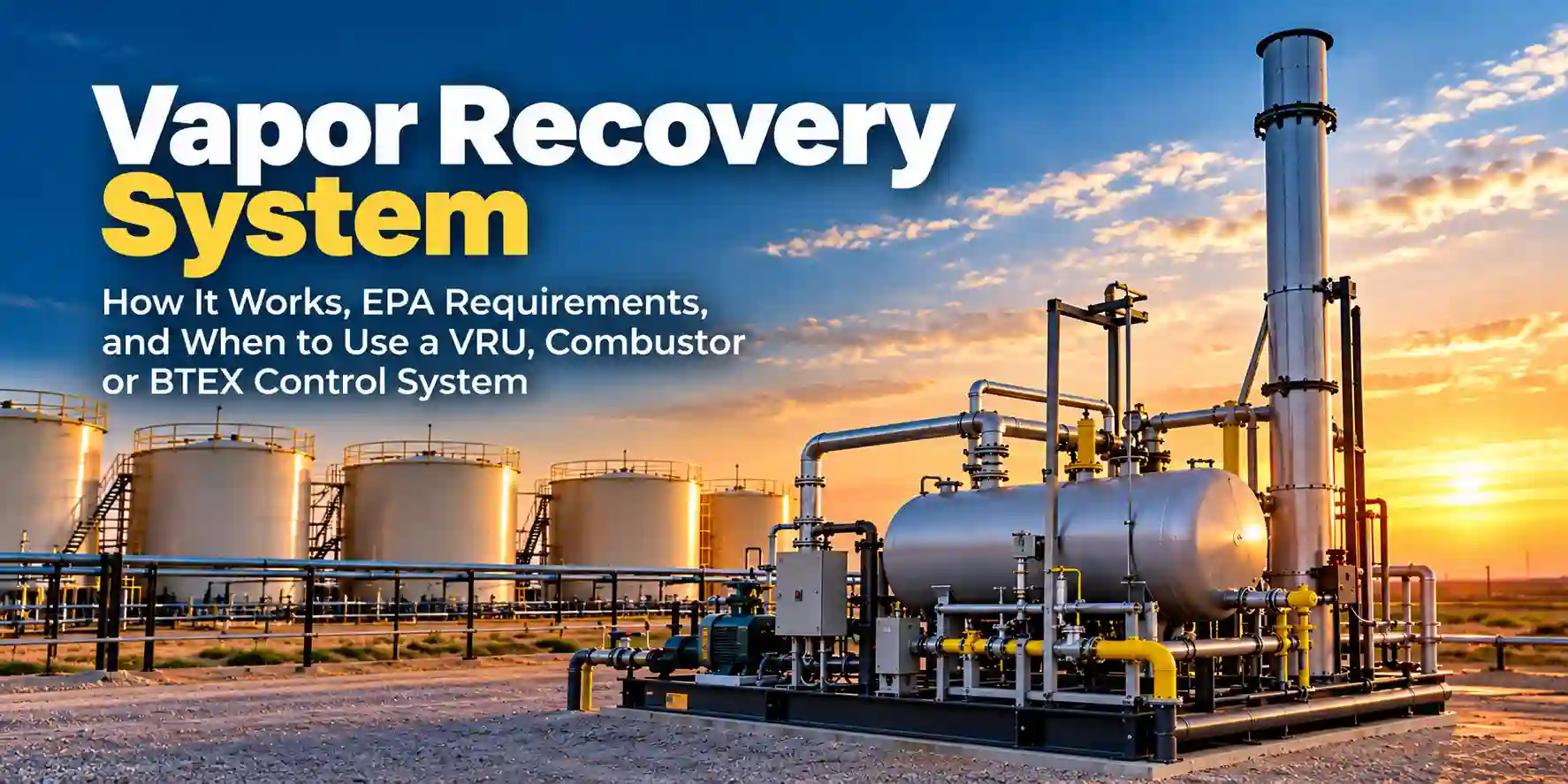
Vapor recovery systems capture gas that would otherwise be vented or flared from storage tanks, separators, and production equipment — and under EPA 40 CFR 60 Subpart OOOOb, the threshold at which a vapor recovery system becomes mandatory has dropped to a level that now affects many tank batteries and well pads that were previously unregulated. Getting the equipment selection right from the start matters: a unit sized for the wrong throughput, or selected without accounting for BTU content, will either underperform or run outside its design envelope within months.
Hero Process Solutions, founded in 2011 with manufacturing in Kellyville, OK and operations in Midland, TX, produces vapor recovery systems, vapor combustors, and BTEX control equipment for upstream production, midstream gathering, and processing applications. The product line covers everything from low-flow combustors at a single well to full VRU packages for multi-tank batteries.
DIRECT ANSWER: Vapor Recovery System
A vapor recovery system (VRS or VRU) is a mechanical system that captures gas vapors from storage tanks and production equipment and either compresses them back into the sales line or routes them to a combustion device for destruction. EPA 40 CFR 60 Subpart OOOOb requires vapor control at storage vessels with VOC emissions at or above 6 tons per year at new or modified production sites.
1. What a Vapor Recovery System Does and How It Works
Storage tanks at production sites accumulate gas in the vapor space above the liquid a mixture of light hydrocarbons (methane, ethane, propane), BTEX compounds (benzene, toluene, ethylbenzene, xylene), and water vapor. Without vapor control, that gas vents to atmosphere through a thief hatch or pressure/vacuum valve every time tank pressure builds from temperature cycling, filling, or flash gas from incoming crude.
A vapor recovery system connects to the tank vapor space and pulls that gas into one of three disposition paths:
Path 1 — Compression and sale: A VRU compressor takes suction on the tank vapor line, compresses the gas to sales-line pressure, and injects it into the gathering system. This recovers the gas as a product and eliminates the emissions entirely.
Path 2 — Vapor combustor destruction: A vapor combustor (VCU) draws the tank vapor under a small negative pressure and burns it at a flare tip or in an enclosed combustor body. No gas recovery the hydrocarbons are destroyed. Used when gas volume is too low to justify compression, or when sales line interconnect is not available.
Path 3 — BTEX condensation and recovery: For tank vapors with high BTEX content, a BTEX condenser system chills the vapor stream to condense the heavy aromatics back to liquid, which is then collected separately. The remaining light gas goes to a combustor or sales line. This is common at crude tank batteries in the Permian Basin where benzene concentrations create additional hazardous air pollutant (HAP) compliance obligations.
KEY INSIGHT
The choice between a VRU compressor, a vapor combustor, and a BTEX condenser is not primarily a cost decision — it is a function of gas volume, gas composition, sales line access, and site permit classification. A site with high BTEX content and no sales line needs a different system than one with lean gas and a nearby gathering connection.
2. EPA Subpart OOOOb: When Is Vapor Recovery Required?
EPA 40 CFR 60 Subpart OOOOb (the “quad-Ob” standard, effective December 2022) extended and tightened requirements for methane and VOC emissions at oil and natural gas production facilities. The key thresholds for storage vessels:
New and modified storage vessels (crude oil, condensate, produced water with hydrocarbon content) require vapor control when the vessel’s potential VOC emissions reach 6 tons per year (tpy) or more. At or above this threshold, the owner/operator must route emissions to a vapor control device achieving at least 95% VOC reduction.
Pneumatic controllers and pumps at well sites also trigger control requirements under OOOOb, which can create additional vapor streams that need to be routed to an approved control device.
State-level requirements in Texas (Texas Commission on Environmental Quality) and Oklahoma (Oklahoma Department of Environmental Quality) may impose additional or earlier-triggering thresholds than federal Subpart OOOOb. The OOOOb compliance page covers the regulatory breakdown for each equipment category.
CRITICAL RULE
EPA 40 CFR 60 Subpart OOOOb requires vapor control at storage vessels with VOC emissions at or above 6 tpy for new or modified sources. The control device must achieve at least 95% VOC reduction. Uncontrolled venting above this threshold is a permit violation subject to EPA enforcement and state air quality penalties.
3. VRU vs. Vapor Combustor vs. BTEX Condenser: Choosing the Right System
| Technology | Best Application | Gas Volume Range | Key Condition | Product Recovery |
|---|---|---|---|---|
| VRU Compressor | Tank batteries with sales line access | 50 MCFD and above | Gas BTU value 900+ BTU/scf | Yes — gas sold |
| Vapor Combustor (VCU) | Low-flow sites, no sales line access | 5–200 MCFD | Self-sustaining combustion required | No — gas destroyed |
| Enclosed Combustor | High-flow combustion without compression | 50–500 MCFD | Requires stable pilot fuel | No — gas destroyed |
| BTEX Condenser | High aromatic content crude tank batteries | Any volume with BTEX present | Requires chiller and condensate handling | Partial — BTEX liquid recovered |
Hero Process Solutions’ vapor combustors are designed for tank battery applications and include a reliable pilot ignition system that meets EPA 40 CFR 60.18 continuously-lit pilot requirements. For high-BTEX crude tank batteries, BTEX control systems are available for both single and multi-tank configurations.
4. How to Size a Vapor Recovery System
Correct sizing of a vapor recovery system requires knowing three things: the flash gas volume, the gas composition, and the operating pressure of the vapor space.
Flash gas volume: This is calculated from your separator gas-to-oil ratio (GOR), the number of stock tanks in the battery, and the fill rate. If separator test data is not available, use API 12J or your state’s AP-42 emission factors as a starting point.
Gas composition (BTU/scf and molecular weight): Tank vapors from crude oil production typically run 1,100–1,400 BTU/scf. Produced water tank vapors may run much lower. Get a vapor sample analysis before specifying the control device lean gas below 300 BTU/scf cannot sustain combustion in a standard open combustor.
Vapor space operating pressure: Tank vapor recovery systems operate under low positive pressure, typically 2 to 8 oz/in² (ounces per square inch). The VRU or combustor inlet must be designed for this low-pressure suction. Specifying a device with a high-pressure minimum inlet will cause it to starve and flame out.
- Calculate maximum daily flash gas volume (MCFD) from separator test data
- Apply a 1.2 peak-to-average factor for daily temperature cycling and filling surges
- Obtain vapor composition analysis (BTU/scf, MW, BTEX concentrations)
- Confirm vapor space operating pressure at the tank
- Select control technology based on the volume/composition/infrastructure matrix
- Match to a unit rated for that throughput at the tank operating pressure
5. Vapor Recovery for Storage Tanks: Tank Battery Configurations
Single-tank or two-tank battery: For small-volume sites (1 to 2 storage tanks, production below 50 BOPD), a single vapor combustor on a shared vapor line is the standard configuration, handling flash gas from both tanks and the separator vent.
Multi-tank battery (3–8 tanks): Larger batteries require a manifolded vapor header connecting all tank vapor lines to a common control device. At this scale, a VRU compressor or an enclosed combustor sized for the combined flash gas volume is typical. Sales line interconnect often makes the VRU the economic choice.
High-pressure separator venting: Separator dump valves and level controllers generate additional vapor pulses when they operate. These streams must be routed to the vapor recovery header, not vented directly to atmosphere.
Hero Process Solutions’ vapor recovery systems are available as skid-mounted packages for tank battery installation, with integral vapor header piping, pilot systems, and instrumentation appropriate for the production site environment.
6. Ignition and Pilot Systems for Vapor Combustors
The most common cause of vapor recovery system compliance failures is pilot outage. A reliable pilot system for a vapor combustor at a remote production site must have:
Electronic auto-ignition: For unmanned or infrequently visited well pads, automatic re-ignition is mandatory. Hero Process Solutions’ ignition systems use electronic spark ignition with automatic retry and a thermocouple-based flame detection circuit.
Independent fuel supply: The pilot fuel must be separate from the vapor being controlled. Using tank vapor as pilot fuel creates a feedback loop where the pilot extinguishes if the tank vapor drops to low flow. Use a dedicated propane supply or a stable instrument gas supply.
Pilot monitoring and alarming: For facilities subject to Subpart OOOOb, pilot flame monitoring with data logging may be required as part of your site compliance documentation.
7. Common Compliance Mistakes at Tank Batteries
| Mistake | Why It Hurts Operations/Compliance | Fix |
|---|---|---|
| Undersized combustor for flash gas volume | Unit flames out during temperature cycling peaks; uncontrolled venting occurs | Size to peak flash gas volume with 1.2 safety factor |
| No vapor header manifold — each tank vented separately | EPA requires all connected storage vessels to route to a single control device | Install vapor header connecting all tank vapor lines to one control device |
| Pilot fuel from the controlled vapor stream | Pilot extinguishes when tank vapor flow drops; emissions violation results | Dedicate a separate propane or instrument gas pilot supply |
| Ignoring BTEX in vapor composition analysis | Benzene in the vapor stream triggers NESHAP HAP requirements beyond Subpart OOOOb | Get full vapor composition analysis including BTEX concentrations before specifying equipment |
| No separator vent control | Flash gas from separator dump is a VOC emission source separate from tank headspace | Route separator vent to the vapor recovery header |
| Using a standard flare instead of an enclosed combustor | Open flares at low flow can fail to meet 95% VOC destruction efficiency at part-load conditions | Use an enclosed combustor rated for the actual low-flow operating condition |
Article Summary
- A vapor recovery system captures gas from storage tanks and production equipment, routing it to compression (VRU) or combustion (combustor) for control.
- EPA 40 CFR 60 Subpart OOOOb requires vapor control at storage vessels with VOC emissions at or above 6 tpy, with a minimum 95% VOC reduction efficiency.
- The choice between a VRU compressor, vapor combustor, and BTEX condenser depends on gas volume, gas composition, sales line access, and HAP compliance obligations.
- VRU compressors are preferred when gas volumes exceed 50 MCFD and pipeline interconnect is available; payback typically runs 12 to 24 months at current gas prices.
- Vapor combustors are the standard low-flow solution (5–200 MCFD) for sites without sales line access; they must meet EPA 60.18 pilot and combustion efficiency requirements.
- Sizing requires flash gas volume from separator test data, vapor composition (BTU/scf and BTEX content), and vapor space operating pressure.
- BTEX condenser systems address HAP compliance at crude oil tank batteries with high benzene concentrations, recovering BTEX as a saleable liquid.
- Pilot system reliability is the most common cause of vapor recovery compliance failures at remote production sites; electronic auto-ignition with independent fuel supply is required.
- Hero Process Solutions manufactures vapor combustors, BTEX control systems, and vapor recovery packages for upstream production, midstream, and processing applications.
Frequently Asked Questions
What is a vapor recovery system in oil and gas?
A vapor recovery system captures hydrocarbon vapors from storage tanks, separators, and production equipment before they vent to atmosphere. The captured gas is either compressed and sold into the gathering system (via a VRU compressor) or routed to a combustion device for destruction. The choice depends on gas volume, composition, and access to a sales line.
When does EPA require a vapor recovery system?
EPA 40 CFR 60 Subpart OOOOb requires vapor control at storage vessels with VOC emissions at or above 6 tons per year for new or modified sources. The control device must achieve at least 95% VOC reduction. State agencies in Texas and Oklahoma may impose additional or lower-threshold requirements.
What is the difference between a VRU and a vapor combustor?
A vapor recovery unit (VRU) uses a compressor to pressurize tank vapors and inject them into the sales gas pipeline, recovering the gas as product. A vapor combustor burns the gas, destroying the hydrocarbons. VRUs are preferred when gas volumes justify compression costs and pipeline access exists. Combustors are used for low-flow sites or where pipeline connection is not feasible.
How do I size a vapor recovery unit?
VRU sizing starts with the maximum flash gas volume from your tank battery, calculated from separator test data or API 12J emission factors. Apply a 1.2 peak-to-average factor for temperature cycling and filling surges, then match to a compressor rated for that throughput at your tank vapor operating pressure (typically 2–8 oz/in²). Gas BTU content and molecular weight also affect compressor selection.
What does BTEX mean in vapor recovery?
BTEX stands for Benzene, Toluene, Ethylbenzene, and Xylene — aromatic compounds present in crude oil and condensate tank vapors. These compounds are Hazardous Air Pollutants regulated under EPA NESHAP rules in addition to the VOC requirements of Subpart OOOOb. Sites with high BTEX concentrations in their tank vapor may need a BTEX condenser system in addition to a standard combustor.
Can a vapor combustor replace a flare at a tank battery?
In many cases, yes. An enclosed vapor combustor achieves higher combustion efficiency than an open flare at low flow rates, making it the preferred control device for tank battery applications where gas volumes are low and variable. Open flares at tank batteries can struggle to maintain 95% VOC destruction efficiency during low-flow periods, while an enclosed combustor with proper residence time and temperature design reliably meets the EPA efficiency requirement.