
OIL & GAS EQUIPMENT | Updated October 2026 | 7 min read
- How a burner management system sequences startup, normal operation and emergency shutdown for industrial flares
- The specific safety interlock requirements under API 556 for flame monitoring and fuel cutoff
- How BMS logic integrates with DCS and SIS platforms in upstream oil and gas operations
- When a standalone safety PLC is required versus when DCS logic alone can satisfy regulatory intent
- Continuous pilot monitoring requirements under EPA 40 CFR 60 Subpart OOOOb
- Flame sensor selection criteria for elevated flares versus enclosed combustors
- Proof-test scheduling requirements by SIL classification
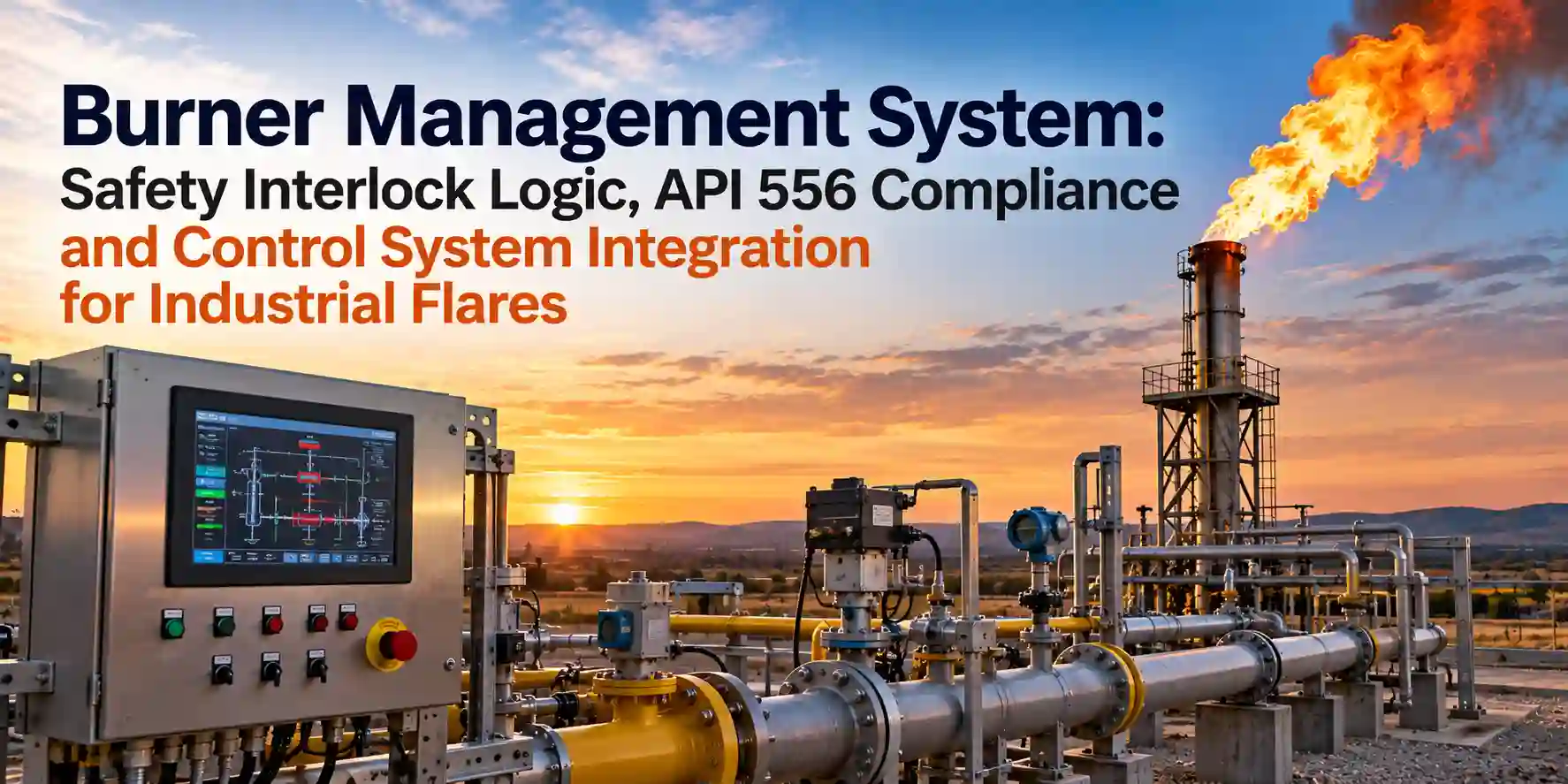
A burner management system is the safety instrumented layer that governs ignition sequencing, flame confirmation and automatic fuel shutoff on any OOOOb-regulated flare or combustion device. Without functional burner management system logic, operators cannot demonstrate the continuous pilot flame monitoring that EPA 40 CFR 60 Subpart OOOOb requires for flares handling volatile organic compound streams from oil and natural gas production.
Hero Process Solutions, founded in 2011 and operating from Kellyville, Oklahoma with a field presence in Midland, Texas, engineers flare systems and combustion equipment for upstream, midstream and refinery clients worldwide. Every flare the company manufactures supports integration with modern BMS platforms, and the engineering team designs interlock logic to API 556 requirements from the initial project scope.
A burner management system is a safety instrumented function that controls the startup, operation and shutdown of combustion equipment through a defined logic sequence. Under API 556 (Instrumentation, Control, and Protective Systems for Gas Fired Heaters), a compliant burner management system must confirm a fuel-free purge period, verify pilot flame before releasing main fuel and execute automatic emergency shutoff on flame failure, high-temperature exceedance or loss of combustion air. For flares covered by EPA 40 CFR 60 Subpart OOOOb, continuous pilot flame monitoring is a regulatory requirement, and burner management system logic is the standard method for satisfying that requirement in automated flare control architectures.
1. How a Burner Management System Controls the Ignition Sequence
The ignition sequence in a well-designed burner management system follows strict step-by-step logic that cannot be bypassed under normal operating conditions. A properly documented ignition sequence reduces the risk of firebox explosions, unburned gas releases and regulatory deviations that would otherwise expose operators to EPA enforcement action.
- Pre-purge: The burner management system opens combustion air dampers and runs a timed purge to clear residual fuel gas before any ignition attempt. Purge volume must be at least five air changes in the firebox, per NFPA 85 requirements.
- Pilot ignition: The BMS energizes the flare ignition system and opens the pilot fuel valve. A UV or flame ionization sensor must confirm stable pilot flame within a defined trial-for-ignition period, typically 10 seconds.
- Main fuel release: Only after pilot flame confirmation does the burner management system open the main fuel control valve, allowing the primary waste gas stream to enter the burner or flare tip.
- Run monitoring: During operation, the BMS continuously checks flame signal strength, fuel pressure and any interlock inputs from the process safety system.
- Safe shutdown: On any interlock trip, the burner management system closes all fuel valves in a defined sequence and holds the combustion device in a safe state until a qualified operator performs a manual reset.
2. Safety Interlock Architecture: Standalone BMS vs. DCS Logic
A frequent design question in oil and gas flare projects is whether the burner management system should run on a dedicated safety PLC or whether DCS logic can handle all interlock functions. The answer depends on the SIL rating required for the safety instrumented function, which is determined through a hazard and operability study (HAZOP) and layers-of-protection analysis (LOPA).
Dedicated safety PLC (recommended for SIL 2 and above): A standalone burner management system runs on separate hardware with redundancy, diagnostics and proof-test intervals verified against IEC 61511. The BMS communicates with the DCS through hardwired I/O for critical interlock signals and through Modbus or OPC-UA for status and alarm data.
DCS-executed BMS logic (SIL 1 or unrated): Some upstream production sites use DCS cause-and-effect matrices to implement burner management functions. This approach is acceptable under API 556 for lower-hazard applications, but the DCS must meet the hardware fault tolerance and diagnostic coverage requirements of the target SIL level. For flare applications handling high-BTU gas streams from condensate or oil production, the additional cost of a certified standalone BMS is typically justified by reduced proof-test burden and cleaner insurance documentation. Enclosed vapor combustors from Hero Process Solutions can be configured with either architecture and ship with as-built interlock documentation.
3. Flame Monitoring Methods and Sensor Selection
The reliability of any burner management system depends directly on the quality of its flame detection. Three sensor technologies are used in flare and combustion applications, and selecting the correct one for the gas composition and installation geometry prevents both nuisance trips and undetected flame failures.
| Detector Type | Best Application | Key Limitation |
|---|---|---|
| UV flame detector | Elevated flare tips, outdoor open flares, natural gas or associated gas streams | Lens contamination in heavy condensate service reduces sensitivity over time |
| Flame ionization (rod-type) | Enclosed combustors, pilot monitoring in low-temperature zones | Not suitable for elevated open flares or high-temperature tip applications |
| Infrared detector | Low-BTU gas combustion, applications with UV signal degradation | More susceptible to false signals from hot process equipment nearby |
For portable or rental flares that must be deployed quickly and relocated between well sites, UV sensors are the standard choice because they require minimal maintenance and perform reliably in open-air outdoor environments typical of Permian Basin and Oklahoma lease operations. NFPA 85 provides additional guidance on flame detector placement and voting logic for combustion systems.
UV sensors lose sensitivity when the detector lens is coated with heavy hydrocarbon deposits from condensate-rich gas streams. Specifying a lens-purge air supply and a scheduled cleaning interval in the burner management system maintenance plan prevents nuisance shutdowns that compromise flare uptime during critical well-test or production startup periods.
4. EPA OOOOb Compliance: Continuous Pilot Monitoring Requirements
Under EPA 40 CFR 60 Subpart OOOOb, operators of affected flares at oil and natural gas production facilities must install a device to monitor the presence of a pilot flame continuously during periods when the flare is receiving regulated gas streams. The rule does not prescribe a specific sensor technology, but the monitoring device must be capable of detecting pilot flame failure and generating an alert within a defined response period.
A properly designed burner management system satisfies this requirement by maintaining a continuous flame signal output from an approved detector during all operating periods, logging flame failure events with timestamps to the plant historian or data logger, alerting operators to loss-of-flame conditions through both local panel alarms and DCS operator station alerts, and recording automatic fuel-valve closure events as evidence of safe shutdown on pilot loss.
Under Subpart OOOOb, a flare that loses pilot flame while receiving a regulated gas stream must be documented as a deviation. Operators must have a corrective action procedure in place before the burner management system is placed in service. Failure to document flame monitoring gaps can trigger excess emissions events requiring notification to the applicable state or federal regulatory authority.
5. Integrating BMS Outputs with Process Safety Systems
In complex production facilities, the burner management system does not operate in isolation. BMS outputs must interface with the process shutdown system (PSD) or safety instrumented system (SIS) to coordinate flare response with upstream process events. Common integration points include emergency depressurization blowdowns, compressor shutdown events and wellhead safety valve closures, all of which can send large volumes of gas to the flare header within seconds.
When a process vessel reaches its high-high pressure setpoint, the PSD triggers a blowdown that routes large gas volumes to the flare header. The burner management system must confirm pilot flame is active before the blowdown sequence opens the flare control valve. Pre-trip signal integration from the compressor package allows the BMS to pre-stage air-assist flares for increased throughput, reducing the risk of smoking or incomplete combustion during gas surge events at gathering stations.
6. Commissioning and Proof-Test Requirements
A burner management system must be function-tested at commissioning and at the proof-test interval required by the SIL classification of the safety instrumented function. For a SIL 1 BMS, proof-test intervals of 12 to 24 months are typical. For SIL 2, annual proof-testing of all interlock channels is generally required to maintain the target probability of failure on demand.
Proof-test procedures for a flare burner management system include simulating flame failure by blocking the UV sensor signal and confirming automatic fuel shutoff within the required response time, verifying the purge timer operation, testing all pressure and temperature interlock inputs, verifying manual shutdown pushbutton operation at both the local panel and the remote DCS workstation, and documenting all test results in the site safety case file. Hero Process Solutions field services include BMS commissioning support and proof-test documentation for new flare installations and replacement combustion systems.
7. Common Mistakes in Burner Management System Design and Operation
| Mistake | Why It Hurts Operations | Fix |
|---|---|---|
| Skipping pre-purge on restart after a trip | Unburned gas in the firebox can ignite explosively on the next spark attempt | Require a mandatory timed purge before every ignition attempt, including restarts after trips |
| Using DCS logic for SIL 2 BMS functions | Standard DCS hardware does not meet the fault tolerance requirements of IEC 61511 for SIL 2 | Install a certified safety PLC with hardware redundancy verified by the vendor safety manual |
| Single UV detector with no redundancy | A single failed sensor causes either spurious trips or undetected flame failures | Use a 2-of-3 voted UV sensor arrangement for flares receiving continuous regulated gas flow |
| Failing to log flame failure events | Loss of monitoring records creates compliance exposure under EPA Subpart OOOOb | Connect BMS event log output to the plant historian and include BMS records in annual compliance reports |
| Neglecting proof-test scheduling | Untested safety functions accumulate unavailability that violates the SIL target probability | Schedule proof-test intervals in the maintenance management system and document each test to the safety case |
Article Summary
- A burner management system controls ignition sequencing, flame monitoring and fuel shutoff for industrial flares and combustion equipment in oil and gas service
- API 556 defines the interlock logic and functional requirements for BMS designs on gas-fired combustion equipment
- EPA 40 CFR 60 Subpart OOOOb requires continuous pilot flame monitoring for affected flares at oil and natural gas production facilities
- UV flame detectors are the standard for outdoor elevated flares; ionization rods are limited to low-temperature pilot monitoring in enclosed applications
- Standalone safety PLCs meeting IEC 61511 are required for SIL 2 BMS applications; DCS logic is acceptable only for SIL 1 or unrated applications
- BMS outputs must integrate with PSD and SIS platforms to coordinate flare response with upstream process shutdown events
- Proof-testing must be performed at commissioning and at the SIL-required interval, with all results documented in the site safety case
- Hero Process Solutions offers BMS-compatible flare systems and field commissioning support for Permian Basin and Oklahoma installations
Frequently Asked Questions
What is a burner management system and why is it required for oil and gas flares?
A burner management system is a safety instrumented function that controls the ignition, operation and shutdown of combustion equipment through a defined, repeatable logic sequence. For oil and gas flares, a BMS is required because EPA 40 CFR 60 Subpart OOOOb mandates continuous pilot flame monitoring on affected flare sources. Without BMS logic to confirm flame status and respond automatically to flame failure, operators cannot demonstrate regulatory compliance during unattended production operations.
What is the difference between API 556 and IEC 61511 for BMS design?
API 556 is a process industry recommended practice that specifies interlock logic, sequence requirements and documentation practices for burner management systems on gas-fired heaters and combustion equipment. IEC 61511 is the international safety instrumented systems standard that defines how to assess the safety integrity level (SIL) of a safety function and verify that hardware and software meet that SIL. A BMS designed to API 556 requirements and implemented on a SIL-rated safety PLC satisfies both documents for most upstream oil and gas flare applications.
Can a DCS handle burner management system logic for a flare?
A distributed control system can execute BMS logic for SIL 1 or unrated applications where consequence severity and risk reduction requirements do not demand higher reliability. For SIL 2 applications, a DCS typically does not meet the hardware fault tolerance and diagnostic coverage requirements of IEC 61511. In those cases, a dedicated safety PLC with certified hardware redundancy is required. The hazard and risk assessment for the specific flare installation determines the required SIL and the acceptable BMS architecture.
How often must a burner management system be proof-tested?
Proof-test intervals for a burner management system depend on the SIL classification of the safety instrumented function. For SIL 1 BMS applications, intervals of 12 to 24 months are common. For SIL 2, annual proof-testing of all interlock channels is typically required to maintain the target probability of failure on demand. The specific interval must be derived from the safety integrity verification calculation and documented in the safety requirements specification for the safety instrumented system.
What happens if a flare loses pilot flame under EPA OOOOb?
Under EPA 40 CFR 60 Subpart OOOOb, a pilot flame failure while the flare is receiving a regulated gas stream constitutes a deviation that must be documented and may require reporting to the applicable regulatory authority. The operator must shut off the gas supply to the flare, investigate the cause of flame failure, restore the pilot before resuming regulated gas routing and record the event in the compliance monitoring log. A burner management system that automatically closes the fuel valve on flame failure and logs the event timestamp is the standard method for managing and documenting these situations.