
OIL & GAS EQUIPMENT | Updated May 2026 | 8 min read
What You’ll Learn in This Guide
- What flare radiation calculation determines and why every flare needs it
- How API 521 defines allowable heat flux limits for personnel and equipment
- Simple radiation methods vs the Brzustowski-Sommer detailed method
- How wind, flame length, and flame tilt affect setback distance
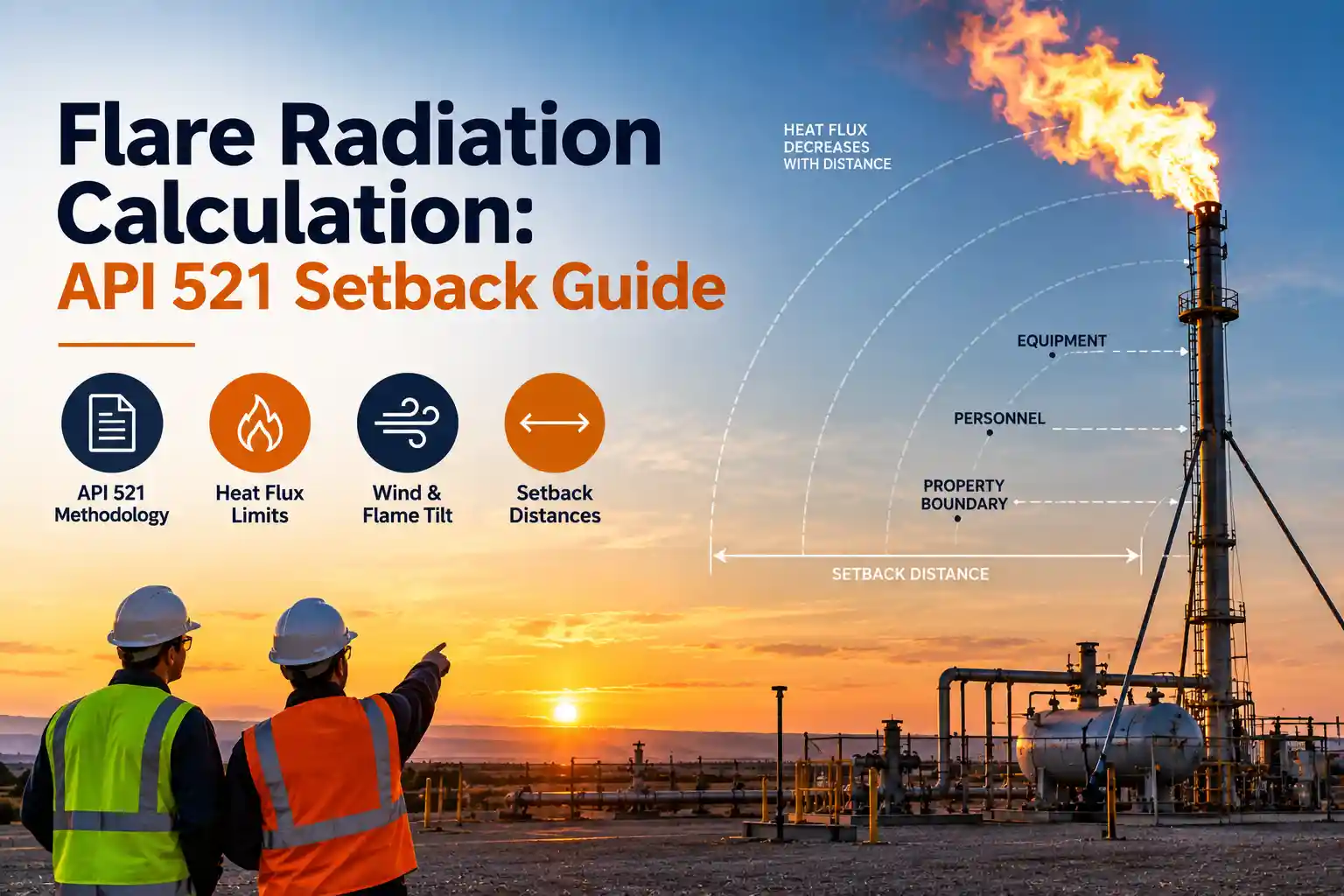
- Setback distances for personnel exposure, equipment, and property boundary
- OOOOb monitoring implications for radiation-driven flare design
- Common flare radiation calculation mistakes and how to avoid them
Flare radiation calculation determines the minimum setback distance between a flare stack and personnel, adjacent equipment, and the facility property boundary. The calculation quantifies how much thermal radiation reaches each location during flare operation, particularly during peak-load relief events, and compares it against allowable heat-flux limits set by API 521 and site-specific safety criteria. Getting this calculation right is fundamental to flare siting and one of the earliest engineering decisions in any flare project.
Hero Process Solutions, founded in 2011 and headquartered in Kellyville, Oklahoma with operations in Midland, Texas, engineers industrial flare systems with radiation-calculation-verified setback distances across upstream, midstream, and refinery service.
DIRECT ANSWER: Flare radiation calculation uses API 521 methodology to quantify thermal radiation at each location around the flare. Simple methods use a point-source assumption with fraction of heat radiated (F factor, typically 0.15, 0.30 depending on flare type). Detailed methods (Brzustowski-Sommer) account for flame length, flame tilt from wind, and location-specific geometry. Allowable heat flux limits: 1,500 Btu/hr-ft² for personnel with escape route, 3,000 Btu/hr-ft² for property boundary, 500 Btu/hr-ft² for continuous exposure. Setback distance is the closest a receptor can be while remaining below its limit at peak flare flow.
1. What Flare Radiation Calculation Determines
Every flare radiates heat during operation. At peak flow, typically an API 521 worst-case relief contingency, the flame is at its largest and radiates the most heat. Personnel in the vicinity, adjacent equipment (tanks, vessels, piping), and the facility property boundary all experience some thermal radiation from the flame.
The radiation calculation determines the heat flux (Btu/hr-ft² or kW/m²) at each location as a function of distance from the flame, flame geometry, and combustion efficiency. Setback distance is then set so that at peak flow, every receptor stays below its applicable heat-flux limit.
2. API 521 Methodology
API 521 (Pressure-relieving and Depressuring Systems) is the primary standard governing flare radiation calculation. Two methods are commonly used.
Simple method (point source): Treats the flame as a single radiating point at the flare tip. Heat flux at a location equals total flame heat release times the fraction radiated (F factor), divided by 4π times distance squared, times atmospheric transmissivity. The F factor accounts for how much of the combustion energy is radiated rather than convected, typically 0.15 for smokeless flares, 0.20 for standard flares, 0.30 for sooty flares.
Detailed method (Brzustowski-Sommer): Models the flame as a tilted cylinder or line source with flame length calculated from gas heat release and buoyancy. Flame tilt from wind is accounted for explicitly. This method is required for accurate calculation near the flare, in windy environments, and for tall flames.
3. Allowable Heat Flux Limits
API 521 defines specific heat flux limits for different exposure scenarios.
Personnel with escape route: 1,500 Btu/hr-ft² (4.73 kW/m²). This applies to areas where personnel could be present but have a clear escape route. The limit reflects that occupants can move away from radiation.
Personnel with continuous exposure: 500 Btu/hr-ft² (1.58 kW/m²). This applies to control room windows, permanent workstations, and other locations where personnel cannot easily leave.
Property boundary (public exposure): Typically 3,000 Btu/hr-ft² (9.46 kW/m²) or site-specific regulatory limits. Sometimes tightened by local air-quality rules or municipal permits.
Equipment (structural steel, tanks): Typically 3,000, 6,000 Btu/hr-ft² depending on equipment sensitivity and paint/insulation.
4. Wind Effects and Flame Tilt
Wind is a major factor in flare radiation calculation. A vertical flame in still air radiates equally in all horizontal directions. A tilted flame under wind moves the flame center laterally, changing which receptors experience peak radiation.
API 521 typically requires the calculation at design wind speed (often 20 mph or the 95th-percentile local wind speed). The flame tilt angle is calculated from wind speed, flame velocity, and buoyancy. For a highly buoyant (hot) flame, tilt is smaller; for a lower-buoyancy flame or high wind, tilt is larger.
The radiation calculation is repeated for multiple wind directions to identify the worst-case receptor location. The setback distance is set by the worst case, not the average.
KEY INSIGHT: Downwind receptors typically experience the highest heat flux because the tilted flame moves toward them. Personnel-access areas, permanent equipment, and control rooms should be positioned upwind of the prevailing wind direction, not downwind, to reduce radiation exposure at peak flow.
5. Determining Setback Distance
Setback distance is the closest a specific receptor can be to the flare while remaining below its applicable heat-flux limit at peak flare flow. The calculation is iterative: pick a candidate distance, calculate heat flux, compare to limit, adjust distance if needed.
For a typical 100 MMSCFD emergency relief flare with a 100-ft stack, personnel setback (with escape route) is often 100, 300 feet, property boundary setback is 200, 500 feet, and control-room setback is 500, 1,000 feet or more depending on the specific calculation results.
Taller flare stacks reduce ground-level heat flux because the flame is elevated, this is one reason large refinery flares run 200, 400 feet tall. The trade-off is capital cost and structural complexity.
6. Peak vs Continuous Flow Cases
Two flow cases drive setback distance: peak relief flow and continuous vent flow.
Peak relief flow is the API 521 worst-case contingency, fire case, power loss, blocked outlet, or similar. This is a rare event but sets the personnel-with-escape-route setback because personnel can move away during a rare event.
Continuous vent flow is the normal operating flow, much smaller than peak but present continuously. This drives the continuous-exposure setback because personnel and equipment experience this radiation constantly.
Both cases are calculated and the more restrictive setback for each receptor type is applied.
7. OOOOb Monitoring Implications
EPA 40 CFR 60 Subpart OOOOb requires 98% Destruction and Removal Efficiency and continuous parametric monitoring on affected-facility flares. Radiation calculation and OOOOb monitoring intersect in three ways.
First, OOOOb-driven changes to flare tip design (air-assisted or sonic to achieve 98% DRE) can change the fraction of heat radiated (F factor), potentially reducing radiation at receptors. Second, continuous vent flow monitoring under OOOOb provides input data for continuous-exposure radiation calculation. Third, OOOOb performance testing at a flare should verify that operating conditions during test remain within the radiation-calculation envelope. See our EPA OOOOb compliance resource for the complete framework.
8. Common Flare Radiation Calculation Mistakes
| Mistake | Why It Hurts | Fix |
|---|---|---|
| Using simple point-source method for tall stacks or close receptors | Under- or over-estimates heat flux | Use Brzustowski-Sommer for tall stacks and close receptors |
| Ignoring wind effects on flame tilt | Underestimates downwind heat flux | Calculate for design wind speed and multiple directions |
| Missing peak-vs-continuous cases | Setback based on wrong case | Calculate both peak relief and continuous vent flow cases |
| Using wrong F factor for flare type | Under-estimates radiation for sooty flares | 0.15 smokeless, 0.20 standard, 0.30 sooty flares |
| Missing municipal or air-quality permit limits | Compliance objection at permit review | Verify property boundary limit with local jurisdiction |
| Using average wind speed instead of design wind | Understates worst-case flame tilt | Use 95th-percentile or API 521-specified wind speed |
Article Summary
- Flare radiation calculation determines minimum setback distance from personnel, equipment, and property boundary.
- API 521 provides two methods: simple point-source and detailed Brzustowski-Sommer with flame tilt.
- Allowable heat flux limits: 1,500 Btu/hr-ft² personnel with escape route, 500 continuous exposure, 3,000 property boundary.
- Wind effects tilt the flame and change the worst-case receptor location, always calculate multiple wind directions.
- Setback distance is set by the worst-case receptor and worst-case wind direction.
- Peak relief flow drives personnel setback; continuous vent flow drives continuous-exposure setback.
- Taller stacks reduce ground-level heat flux at the cost of capital and structural complexity.
- OOOOb tip changes (air-assist, sonic) can reduce F factor and improve radiation compliance.
Related resources: Review our companion articles on API 537 flare system design, flare system safety standards, and latest flare innovations. For OOOOb requirements, see EPA flare monitoring rules. Learn about our field services.
Frequently Asked Questions
What is flare radiation calculation?
Flare radiation calculation quantifies the thermal radiation (heat flux, Btu/hr-ft²) at each location around a flare during operation. It determines the minimum setback distance between the flare stack and personnel-access areas, adjacent equipment, and the facility property boundary so that each receptor stays below its allowable heat-flux limit.
What are the API 521 heat flux limits?
1,500 Btu/hr-ft² (4.73 kW/m²) for personnel with a clear escape route; 500 Btu/hr-ft² (1.58 kW/m²) for continuous exposure like control-room windows; 3,000 Btu/hr-ft² (9.46 kW/m²) or site-specific regulatory limits for property boundary. Equipment limits are typically 3,000, 6,000 Btu/hr-ft² depending on sensitivity.
Simple or detailed radiation method?
Simple point-source is adequate for preliminary screening and far-field receptors. The detailed Brzustowski-Sommer method is required for tall stacks, close receptors, and windy environments where flame tilt significantly affects heat flux. Most engineering projects use both, simple method for screening, detailed for the critical setback determinations.
How does wind affect flare radiation?
Wind tilts the flame from vertical, moving the effective flame position and changing which receptors experience peak heat flux. Downwind receptors typically see the highest radiation. API 521 calculations use design wind speed (typically 20 mph or 95th-percentile local wind) and cover multiple wind directions to identify worst-case setback.
Does taller stack help with radiation?
Yes. Elevating the flame reduces ground-level heat flux because the geometric distance to receptors increases and the atmospheric attenuation is greater. Large refinery flares run 200, 400 feet tall partly for this reason. The trade-off is capital cost, structural steel, and construction complexity.
Is radiation calculation part of OOOOb compliance?
Radiation calculation is not directly part of OOOOb, but OOOOb-driven tip design changes (air-assist or sonic to achieve 98% DRE) can change the F factor and reduce radiation. OOOOb continuous vent monitoring also provides input data for continuous-exposure radiation calculation. Well-designed flare systems integrate both.