
FLARE ENGINEERING STANDARDS | Updated August 2026 | 9 min read
WHAT YOU’LL LEARN IN THIS GUIDE
- What API Standard 537 covers and which facilities are required to follow it
- How API 537 defines flare tip velocity limits, pressure drop, and smokeless capacity
- The difference between API 537 and API 521 and why both matter for flare system design
- Pilot flame monitoring requirements under API 537
- How API 537 relates to EPA 40 CFR 60 Subpart OOOOb compliance
- Flare tip types covered by the standard and their selection criteria
- How to apply API 537 when specifying a new flare system or upgrading an existing one
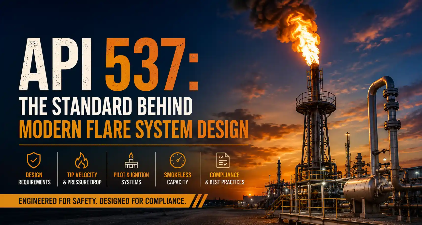
API 537 is the primary published standard governing flare details for refinery and petrochemical service, and it is the document that engineers reference when specifying a new flare tip, evaluating pilot flame monitoring systems, or calculating allowable tip exit velocities. Understanding what the standard requires, and where it does not apply, is the starting point for any flare system specification in a regulated facility.
Hero Process Solutions, founded in 2011 and headquartered in Kellyville, Oklahoma with operations in Midland, Texas, manufactures combustion equipment designed to meet API 537 requirements for refinery, petrochemical, and upstream oil and gas applications. This guide explains what the standard covers and how it should inform your flare system selection and specification process.
DIRECT ANSWER: API 537
API Standard 537, “Flare Details for General Refinery and Petrochemical Service,” is an American Petroleum Institute standard that specifies design, materials, and testing requirements for flare systems used in the petroleum refining and petrochemical industries. The standard covers flare tip types, tip exit velocity limits, pressure drop calculations, pilot flame systems, ignition systems, and steam- and air-assist requirements. API 537 is currently in its third edition (2017) and is cited in facility permit applications and engineering specifications as the design basis for code-compliant flare systems at refineries and gas processing plants.
1. Scope and Applicability of API Standard 537
API 537 applies to flare systems installed at petroleum refineries, petrochemical plants, and natural gas processing facilities. The standard specifically addresses elevated flares, ground-level flares, enclosed combustors, and the associated piping, knockout drums, and auxiliary systems that make up a complete flare installation.
The scope includes:
- Flare tip design and materials
- Flare tip exit velocity calculations and limits
- Pressure drop through the flare tip and riser
- Smokeless operation capacity and assist medium selection
- Pilot flame systems: fuel supply, pilot tip design, and ignition
- Flame monitoring instrumentation
- Steam, air, and gas assist systems
- Flare knockout drum sizing (in conjunction with API 521)
API 537 does not cover the upstream relief and depressurization system design, which falls under API 521 (“Pressure-Relieving and Depressurizing Systems”). In practice, a flare system specification at a major refinery or petrochemical facility references both standards: API 521 for relief load sizing and header design, and API 537 for the flare tip and pilot system design details.
2. Flare Tip Types Covered by API 537
The third edition of API 537 organizes flare tips into categories based on their combustion assist mechanism and application. Each type has specific design requirements and selection criteria within the standard.
Utility flares. Simple unassisted flare tips for low-flow or intermittent service where smokeless operation is not required. Utility flares have the lowest capital cost but are limited to streams where visible smoke is acceptable and flow rates are modest. The utility flares from Hero Process Solutions are available in configurations that meet API 537 materials and velocity requirements for this service class.
Steam-assist flares. Flare tips that inject steam at the tip to promote turbulent mixing and suppress visible smoke. API 537 provides steam-to-gas ratio guidance for achieving smokeless combustion at specified mass flow rates. Steam-assist tips are the historical standard in refineries where steam is available and smokeless operation is required at high flow rates.
Air-assist flares. Flare tips that use blower-forced air to achieve smokeless combustion. API 537 addresses air assist design including blower sizing, air-to-gas ratios, and tip velocity requirements. The air-assist flares product line at Hero Process Solutions covers elevated configurations with forced-draft air systems designed per API 537 requirements.
Gas-assist flares. Flare tips that use a supplemental fuel gas to maintain stable combustion and achieve smokeless operation with low-BTU or variable-composition waste gas. Gas-assist designs are referenced in API 537 for applications where steam or air is not practical.
Ground-level enclosed flares and combustors. API 537 Section 6 addresses enclosed ground flare and combustor design requirements, including combustion chamber sizing, turndown ratio, and exhaust stack design. The vapor combustors at Hero Process Solutions are designed in accordance with the enclosed combustion principles in API 537 Section 6.
3. Flare Tip Exit Velocity: The Core API 537 Calculation
The maximum allowable exit velocity at the flare tip is one of the central calculations in API 537. Velocity limits exist for two reasons: preventing flameout at low flow and preventing blowout or flame instability at maximum flow.
API 537 uses a dimensionless Mach number-based approach for high-pressure tips, and a foot-per-second limit for lower-pressure utility tip designs. The standard provides equations for calculating the maximum allowable velocity based on waste gas molecular weight and lower heating value, ensuring that the combustion zone remains stable under peak relief flow conditions.
KEY INSIGHT
API 537 exit velocity limits are not arbitrary. A tip operating above the maximum allowable velocity under peak relief conditions risks blowout, where the flame lifts off the tip and extinguishes. A blowout during a major relief event releases unburned hydrocarbons to atmosphere, creating both a safety hazard and an air quality permit violation. Sizing the tip correctly for the design relief case, not just the normal operating case, is the most common mistake engineers make when specifying a flare to API 537 requirements.
4. Pilot Flame Systems Under API 537
API 537 dedicates a full section to pilot flame system design, reflecting the critical role pilots play in ensuring reliable ignition and sustained combustion. The standard addresses:
Number of pilots. API 537 provides guidance on the minimum number of pilot burners based on flare tip diameter and design flow rate. Large-diameter tips require multiple pilots distributed around the tip circumference to ensure ignition coverage.
Pilot gas supply. The standard requires that pilot gas be clean, stable, and segregated from the waste gas stream. Pilot gas supply pressure and heating value must be sufficient to maintain a stable pilot flame under the worst-case cross-wind conditions at the site.
Pilot tip design. API 537 specifies materials and tip geometry for pilots that must survive continuous operation in the flare flame environment, including high-temperature alloy requirements for pilot tips exposed to radiant heat from the main flame.
Flame monitoring. Thermocouple-based or ultraviolet (UV) sensor-based pilot flame monitoring systems are addressed in API 537. For facilities subject to EPA 40 CFR 60 Subpart OOOOb, pilot flame monitoring is also a compliance requirement, and the API 537 design requirements align with what EPA monitoring rules mandate. The ignition systems from Hero Process Solutions include pilot monitoring configurations that satisfy both API 537 and OOOOb requirements.
5. API 537 vs. API 521: Understanding the Difference
Engineers new to flare system design sometimes conflate API 537 and API 521. The two standards cover different parts of the flare system and must be used together for a complete design.
| Topic | API 521 | API 537 |
|---|---|---|
| Primary purpose | Relief system design and sizing | Flare tip and auxiliary system design |
| Covers | Relief valves, depressurizing systems, relief headers, knockout drums | Flare tips, pilots, ignition, steam/air/gas assist |
| Velocity calculations | Relief header sizing (two-phase flow, pressure drop) | Flare tip exit velocity limits |
| KO drum | Sizing basis (vapor-liquid separation) | References API 521; does not re-derive sizing |
| Enclosed combustors | Not covered | Section 6 covers ground-level enclosed designs |
| Current edition | 6th edition (2014, addendum 2017) | 3rd edition (2017) |
6. API 537 and EPA 40 CFR 60 Subpart OOOOb
For upstream oil and gas facilities subject to EPA 40 CFR 60 Subpart OOOOb, API 537 is not directly cited in the regulation, but it is the design standard that engineers use to demonstrate that a flare system meets the combustion efficiency and pilot flame monitoring requirements in OOOOb.
Subpart OOOOb requires 98% combustion efficiency for flares at affected facilities, plus continuous pilot flame monitoring (thermocouple or equivalent). API 537 pilot design and flame monitoring requirements are the engineering basis for flares that meet these performance standards. When submitting a flare design for permit review under OOOOb, citing API 537 as the design basis establishes a credible engineering foundation for the permit application.
Hero Process Solutions provides OOOOb compliance support including flare tip design documentation that references API 537 for facilities seeking permit approval or demonstrating compliance with performance testing requirements.
7. Applying API 537 When Specifying a New Flare System
API 537 is a design specification document, not a prescriptive checklist. Applying it correctly requires engineering judgment at several decision points.
Define the design cases first. API 537 tip velocity and assist medium sizing calculations require a defined design relief load. The design case is typically the maximum credible relief scenario from the process hazard analysis, not the normal operating flow rate. Using the wrong design basis is the most common sizing error.
Select the tip type before sizing. Tip type selection (utility, steam-assist, air-assist, gas-assist) drives the sizing methodology in API 537. Each tip type has different velocity limits, turndown considerations, and smokeless capacity approaches. Tip type selection should be based on site utilities availability, smokeless requirements, and throughput range before sizing calculations begin.
Address turndown explicitly. API 537 requires flare tips to maintain stable combustion from maximum design flow down to minimum operating flow. Turndown ratio requirements drive pilot sizing and, for air-assist designs, blower control system design. A tip sized only for the design case without verifying low-flow stability will fail at minimum flow conditions.
Contact Hero Process Solutions at sales@hero-ps.com or (918) 941-2166 to discuss API 537-compliant flare system configurations for refinery, petrochemical, or upstream production applications. Field services include API 537 design review and commissioning support for new installations.
Article Summary
- API Standard 537 is the primary design standard for flare tips in refinery and petrochemical service, covering tip types, exit velocity limits, pressure drop calculations, pilot systems, and assist medium design.
- The standard is currently in its third edition (2017) and covers utility flares, steam-assist flares, air-assist flares, gas-assist flares, and enclosed ground-level combustors.
- API 537 and API 521 address different parts of the flare system. API 521 covers relief system sizing and header design; API 537 covers flare tip and auxiliary system design. Both are required for a complete flare system specification at a regulated facility.
- Flare tip exit velocity is the central API 537 calculation. Tip sizing must address both the maximum relief case (blowout prevention) and minimum operating case (flameout prevention).
- Pilot flame monitoring requirements in API 537 align with EPA 40 CFR 60 Subpart OOOOb monitoring requirements, making API 537 the practical engineering basis for OOOOb-compliant flare pilot systems.
- Tip type selection must precede sizing: the design methodology and velocity limits in API 537 differ by tip type, and selecting the wrong tip type for the application invalidates the subsequent calculations.
- Hero Process Solutions manufactures API 537-compliant flare systems from its Kellyville, Oklahoma facility for refinery, petrochemical, and upstream production service.
Frequently Asked Questions
What is API 537 and what does it cover?
API Standard 537, “Flare Details for General Refinery and Petrochemical Service,” is an American Petroleum Institute standard that specifies design requirements for flare tips, pilot systems, ignition systems, and steam, air, and gas assist systems for flares installed at petroleum refineries, petrochemical plants, and natural gas processing facilities. The current edition is the third (2017). API 537 is the primary design reference for flare tip engineering at major industrial facilities and is commonly cited in permit applications as the design basis for code-compliant flare systems.
What is the difference between API 537 and API 521?
API 521 covers the design of pressure-relieving and depressurizing systems, including relief valves, relief headers, and flare knockout drum sizing. API 537 covers the design of the flare tip itself and associated auxiliary systems, including pilot flames, ignition, and steam or air assist. A complete flare system design at a regulated facility requires both standards: API 521 for the upstream relief system and API 537 for the flare combustion equipment.
Does API 537 apply to upstream oil and gas production facilities?
API 537 is written for refinery and petrochemical service, but its design principles including tip velocity limits, pilot system requirements, and assist medium sizing are widely applied to upstream production flares as well. For upstream facilities subject to EPA 40 CFR 60 Subpart OOOOb, API 537 design criteria are used as the engineering basis for demonstrating compliance with combustion efficiency and pilot monitoring requirements, even though OOOOb does not directly cite the standard.
What are the pilot flame monitoring requirements in API 537?
API 537 requires continuous pilot flame monitoring for flare systems in regulated service. Acceptable monitoring approaches include thermocouple-based detection and ultraviolet (UV) flame sensor detection. The monitoring system must provide an alarm on pilot flame failure and, for some facility types, initiate automatic re-ignition. These requirements align with EPA OOOOb pilot monitoring rules, which mandate continuous pilot flame monitoring at affected facilities.
How does API 537 address smokeless flare operation?
API 537 provides assist medium sizing guidance for achieving smokeless combustion at specified flow rates. For steam-assist designs, the standard provides steam-to-gas ratios by waste gas type. For air-assist designs, blower sizing and air-to-gas ratios are addressed. Smokeless capacity is defined as the maximum waste gas flow rate at which the flare tip can combust without producing visible smoke, and API 537 requires that this capacity be established during the design phase based on the site’s smokeless operation requirement.
Does Hero Process Solutions manufacture API 537-compliant flare systems?
Yes. Hero Process Solutions designs and manufactures flare systems to API 537 requirements for refinery, petrochemical, and upstream gas service. Product lines include utility flares, air-assist flares, and enclosed combustors in configurations that meet API 537 materials, velocity, and pilot system requirements. Contact sales@hero-ps.com or (918) 941-2166 for application-specific design support.