OIL & GAS EQUIPMENT | Updated May 2026 | 8 min read
What You’ll Learn in This Guide
- What EPA 40 CFR 60 Subpart OOOOb changes for air assisted flares
- Why fixed-speed blowers cannot meet OOOOb
- How VFD blower control logic achieves 98% DRE across the full operating range
- What continuous parametric monitoring instrumentation is required
- How annual performance testing under EPA Methods 18, 25A, and 25B works
- What recordkeeping and CEDRI reporting obligations apply
- How to specify an OOOOb-ready air assisted flare from day one
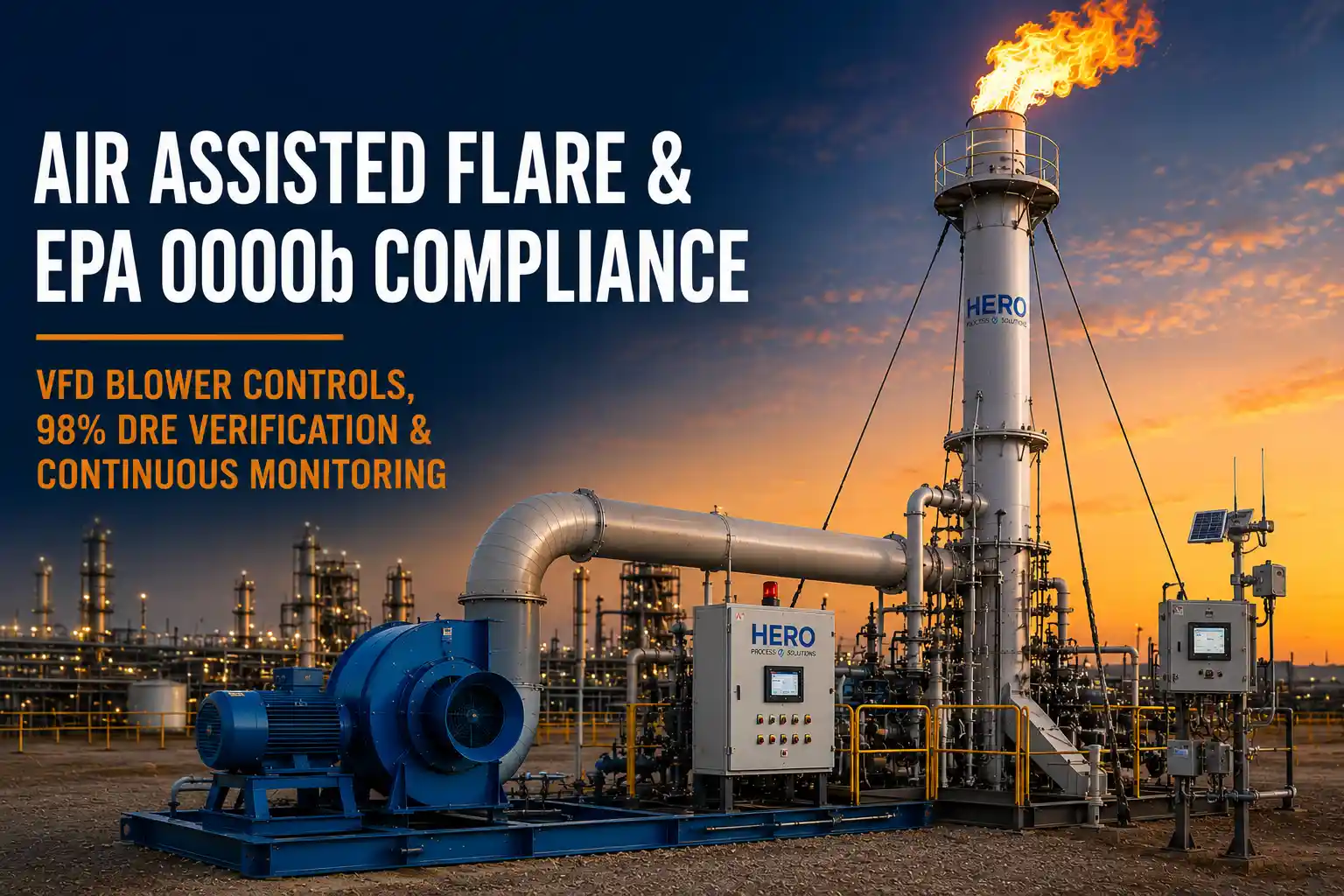
EPA 40 CFR 60 Subpart OOOOb changed the engineering brief for every air assisted flare specified in the United States. Where the prior NSPS standard (Subpart OOOOa) accepted 95% Destruction and Removal Efficiency for most flare configurations, OOOOb raises the bar to 98% DRE and adds explicit continuous monitoring, performance testing, and recordkeeping obligations on affected oil and natural gas facilities. For an air assisted flare, which depends on precise air-to-gas mass-ratio control to achieve smokeless, high-efficiency combustion, those requirements drive design decisions that must be locked in before fabrication.
Hero Process Solutions, founded in 2011 and headquartered in Kellyville, Oklahoma with operations in Midland, Texas, manufactures the A+ Series air assisted flare systems line as a turnkey OOOOb-ready package. This guide walks through what OOOOb actually requires of an air assisted flare, how a Variable Frequency Drive blower delivers 98% DRE, and what monitoring and recordkeeping protocols a compliant facility must put in place.
DIRECT ANSWER: EPA 40 CFR 60 Subpart OOOOb requires air assisted flares on affected oil and natural gas sources to achieve 98% Destruction and Removal Efficiency, continuously monitor pilot and combustion zone presence and vent-gas flow, pass annual performance tests using EPA Methods 18, 25A, or 25B, and retain records for five years with reporting via CEDRI. 98% DRE on an air assisted flare is only achievable with a Variable Frequency Drive blower that maintains the correct air-to-gas mass ratio across the full operating range.
1. What Subpart OOOOb Changes for an Air Assisted Flare
EPA finalized 40 CFR 60 Subpart OOOOb (Standards of Performance for Crude Oil and Natural Gas Facilities) and the related Subpart OOOOc emissions guidelines for existing sources in 2024, with phased implementation continuing through 2026. For affected facilities — well sites, gathering and boosting stations, natural gas processing plants, and certain transmission and storage compressor stations — flares used as control devices are subject to specific performance and monitoring requirements. The full EPA OOOOb / OOOOc rule applies across these facilities.
The most consequential changes for an air assisted flare specification are these. The destruction efficiency standard rises from 95% to 98% DRE for routine operating conditions. Continuous parametric monitoring of pilot flame presence, combustion zone activity, and vent-gas flow is required during all periods of waste-gas flow. Annual performance testing must demonstrate continued compliance with the 98% DRE standard. Records must be retained for five years and reports submitted electronically through EPA’s CEDRI portal. Visible-emissions limits are tightened, narrowing the prior allowance for short smoking periods under 40 CFR 60.18.
For an air assisted flare specifically, 98% DRE is only achievable if the air-to-gas ratio is actively controlled across the full operating range. That single requirement reshapes the engineering brief.
2. Why Fixed-Speed Blowers Cannot Meet OOOOb
A fixed-speed blower delivers a constant volume of combustion air regardless of waste-gas flow rate. At peak design flow the air-to-gas ratio is correct. But during normal operation, when waste-gas flow may sit at 10 to 30 percent of peak, a fixed-speed blower over-supplies combustion air. Excess air at the tip cools the flame, depresses combustion efficiency, can blow the flame off the tip entirely, and drops DRE below the 98 percent threshold. The air assisted flare passes its initial performance test at peak flow and then operates non-compliantly during routine service.
KEY INSIGHT: OOOOb is not a snapshot standard. EPA requires 98% DRE to be maintained, monitored, and documented across all operating conditions — not just at the single peak flow at which the initial performance test is conducted. A fixed-speed blower satisfies the test and violates the rule.
The fix is straightforward: a Variable Frequency Drive on the blower motor, paired with a flow transmitter on the inbound vent-gas line and a control loop that modulates blower speed to maintain the target air-to-gas mass ratio at every operating point.
3. How VFD Blower Control Logic Delivers 98% DRE on an Air Assisted Flare
The control logic for an OOOOb-grade air assisted flare is a closed-loop system. A flow transmitter measures vent-gas mass flow in real time. The Programmable Logic Controller (PLC) or Distributed Control System (DCS) calculates the required combustion air mass flow based on vent-gas composition and the design air-to-gas ratio. The VFD adjusts blower speed to deliver the calculated air flow. A combustion-zone thermocouple or flame ionization detector confirms the main flame is present and stable. If the flame is lost, the ignition system relights automatically and the event is logged for compliance records.
Key tuning parameters include the target air-to-gas mass ratio (typically 0.30 to 0.50 lb air per lb gas for produced-gas streams, higher for olefin-rich streams), the minimum stable blower speed (typically 10 to 20 percent of full speed), the maximum slew rate (how fast the blower ramps for transient flow spikes), and the loss-of-flame response time. The redundant pilot ignition system relights within seconds and logs each event.
The result is an air assisted flare that holds 98% or greater DRE during steady-state operation, during normal flow excursions, and during emergency relief events, which is exactly what OOOOb requires.
4. Continuous Parametric Monitoring Requirements
Subpart OOOOb requires continuous monitoring of three flare operating parameters during all periods of waste-gas flow.
Pilot flame presence must be verified continuously. This is typically done with a redundant thermocouple and ionization-rod arrangement at the pilot. Combustion zone presence (the main flame) must be verified using a video flame monitor, a combustion-zone thermocouple, or a flame ionization detector. Vent-gas flow rate and composition must be measured to calculate net heating value and, for an air assisted flare, to drive the VFD air-to-gas ratio control loop.
All three parameters must be recorded at intervals frequent enough to detect non-compliance events. Most facilities log at 15-second to 1-minute intervals. The data must be retained for five years and made available to EPA on request.
CRITICAL RULE: Redundant sensing is not optional. Single-point pilot or combustion-zone monitoring creates a single point of failure that, when it fails, triggers an OOOOb deviation event the moment the next data interval is logged. Specify redundant pilot and combustion-zone monitors from day one.
Hero’s standard A+ Series instrumentation package includes redundant pilot monitoring, a thermocouple-based combustion-zone monitor with optional video flame backup, a Coriolis or ultrasonic vent-gas flow meter, and a PLC-based historian that captures parametric data and pushes it to the operator’s compliance system.
5. Annual Performance Testing Under EPA Methods 18, 25A, and 25B
Initial and annual performance tests demonstrate that the air assisted flare actually achieves 98% DRE. The test methodology depends on the vent-gas composition and the facility’s permit conditions.
EPA Method 18 (gas chromatography) is typically used to speciate the vent-gas inlet stream. Method 25A or 25B is used to measure total hydrocarbons at the flare outlet. DRE is calculated as the percentage of inlet vent-gas carbon destroyed in the combustion zone.
For an air assisted flare to pass annual testing, three conditions must be satisfied at the test. Sample ports must be installed at locations compliant with EPA Method 1. The VFD control loop must be operating correctly at test conditions, holding the design air-to-gas ratio. And the pilot, combustion-zone monitor, and flow instrumentation must all be functional and within calibration.
Hero’s commissioning protocol includes pre-test verification of all three conditions. The Hero field commissioning and testing support team supports customers through the initial OOOOb performance test and subsequent annual recertifications.
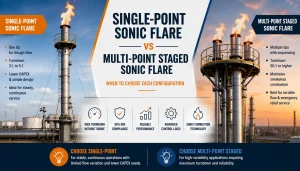
6. Air Assisted Flare OOOOb Compliance Comparison Across Configurations
| Configuration | Meets OOOOb 98% DRE? | OPEX Impact | Compliance Risk |
|---|---|---|---|
| Fixed-speed blower air assisted flare | No (peak only) | Higher (constant air OPEX) | High — deviations on every turndown |
| VFD blower, single pilot monitor | Yes, with risk | Lower | Medium — single-point failure on pilot |
| VFD blower, redundant pilot, redundant combustion-zone monitor (Hero A+ standard) | Yes | Lower | Low — designed for OOOOb from day one |
| Manual air damper, no VFD | No | Variable | Very high — fails performance and monitoring |
The Hero A+ Series standard configuration in the broader industrial flare systems line is the lowest-risk, lowest-compliance-cost pathway for an OOOOb air assisted flare.
7. Recordkeeping and CEDRI Reporting
OOOOb compliance documentation for an air assisted flare must include: the design specification (peak flow, smokeless capacity, blower HP, stack height, VFD control range), the initial performance test report, all continuous parametric monitoring data for the prior five years, all annual recertification test reports, all flame-loss events with timestamp and root cause, and all maintenance and calibration records for the monitoring instrumentation.
Reports are submitted electronically through CEDRI on the schedule set in the facility’s compliance plan. Routine reports are typically annual. Deviation reports must be submitted within 30 days of the event.
8. How to Specify an OOOOb-Ready Air Assisted Flare from Day One
Before placing a purchase order for an air assisted flare on a new or modified affected facility, verify the specification includes the following items: a VFD blower with control loop tuned for 98% DRE across the full turndown; continuous pilot and combustion-zone monitoring with redundant sensors; a vent-gas flow meter with accuracy and turndown matched to the air-to-gas ratio calculation; sample ports compliant with EPA Method 1 for annual performance testing; a PLC-based data historian with five-year retention; and a commissioning plan that includes the initial OOOOb performance test.
Hero’s A+ Series air assisted flare ships from Kellyville, Oklahoma as a turnkey OOOOb-ready package: VFD blower, redundant monitoring, factory-tuned control logic, sample ports per Method 1, historian, and field commissioning support included.
9. Common Mistakes in Air Assisted Flare OOOOb Compliance
| Mistake | Why It Hurts Compliance | Fix |
|---|---|---|
| Specifying a fixed-speed blower to save CAPEX | Cannot hold 98% DRE outside peak design flow | Specify VFD with closed-loop air-to-gas control |
| Single pilot or combustion-zone sensor | Single-point failure becomes a deviation event | Specify redundant sensing on both pilot and main flame |
| Sample ports retrofitted after fabrication | Often fail EPA Method 1 sample-location criteria | Locate ports during fabrication, verified to Method 1 |
| Data logged at intervals too sparse to detect deviations | Cannot demonstrate continuous compliance | Log at 15-second to 1-minute intervals minimum |
| Ignoring CEDRI deadlines | Late filing triggers enforcement | Calendar annual and deviation deadlines at commissioning |
| Treating OOOOb as a one-time test | Initial pass does not guarantee ongoing compliance | Set up annual recertification protocol with HPS field services |
Frequently Asked Questions
What DRE does EPA 40 CFR 60 Subpart OOOOb require for an air assisted flare?
Subpart OOOOb requires 98% Destruction and Removal Efficiency for routine operating conditions on affected oil and natural gas facilities. This is up from the 95% threshold under the prior Subpart OOOOa standard. For air assisted flares, the 98% standard must be maintained across the full operating range, not just at the peak flow at which the initial performance test is conducted.
Does OOOOb require a VFD blower on every air assisted flare?
EPA does not specify a VFD by name, but the 98% DRE requirement across the full operating range is not achievable with a fixed-speed blower. A fixed-speed blower over-supplies air during turndown, dropping combustion efficiency below 98%. A VFD-controlled blower modulating to the measured vent-gas flow is the standard pathway to OOOOb compliance for air assisted flares.
What instrumentation does OOOOb require on an air assisted flare?
Continuous monitoring is required for pilot flame presence (typically redundant thermocouple and ionization rod), combustion zone presence (video flame monitor, combustion-zone thermocouple, or flame ionization detector), and vent-gas flow rate. Data must be logged at intervals frequent enough to detect deviations, typically 15 seconds to 1 minute, and retained for five years.
Which EPA test methods are used for the annual OOOOb performance test?
EPA Method 18 (gas chromatography) is typically used to speciate the vent-gas inlet stream, and Methods 25A or 25B measure total hydrocarbons at the flare outlet. DRE is calculated as the percentage of inlet vent-gas carbon destroyed. Sample ports must be placed in compliance with EPA Method 1.
How are OOOOb compliance reports submitted?
Reports are submitted electronically through EPA’s Compliance and Emissions Data Reporting Interface (CEDRI). Routine reports are typically annual, on the schedule set in the facility’s compliance plan. Deviation reports must be submitted within 30 days of the event. Records supporting reports must be retained for five years.
Can Hero Process Solutions support OOOOb performance testing in the field?
Yes. Hero Process Solutions’ field services team supports customers through pre-test verification of VFD control logic, pilot and combustion-zone monitor calibration, sample-port verification to EPA Method 1, the initial OOOOb performance test, and annual recertification testing. This service is included as part of the A+ Series turnkey package.