OIL & GAS EQUIPMENT | Updated May 2026 | 7 min read
What You’ll Learn in This Guide
- How to define the design basis for an air assisted flare using peak flow and gas composition
- How to calculate smokeless capacity correctly using air-to-gas mass ratio
- How to size blower horsepower for routine and emergency relief service
- How to set stack height using API Standard 521 radiation and dispersion criteria
- Why a Variable Frequency Drive blower is required for OOOOb 98% DRE
- How to specify turndown ratio for combined continuous and emergency service
- Common air assisted flare sizing mistakes and how to avoid them
Specifying the wrong air assisted flare for an oil and gas facility is one of the most expensive engineering mistakes a project team can make. Undersize the blower and the flare smokes during peak releases, triggering EPA visible-emission violations under 40 CFR 60.18. Oversize the stack and capital costs climb while turndown performance suffers at normal operating rates. Set the smokeless capacity incorrectly and the air assisted flare fails its Destruction and Removal Efficiency test on day one of commissioning.
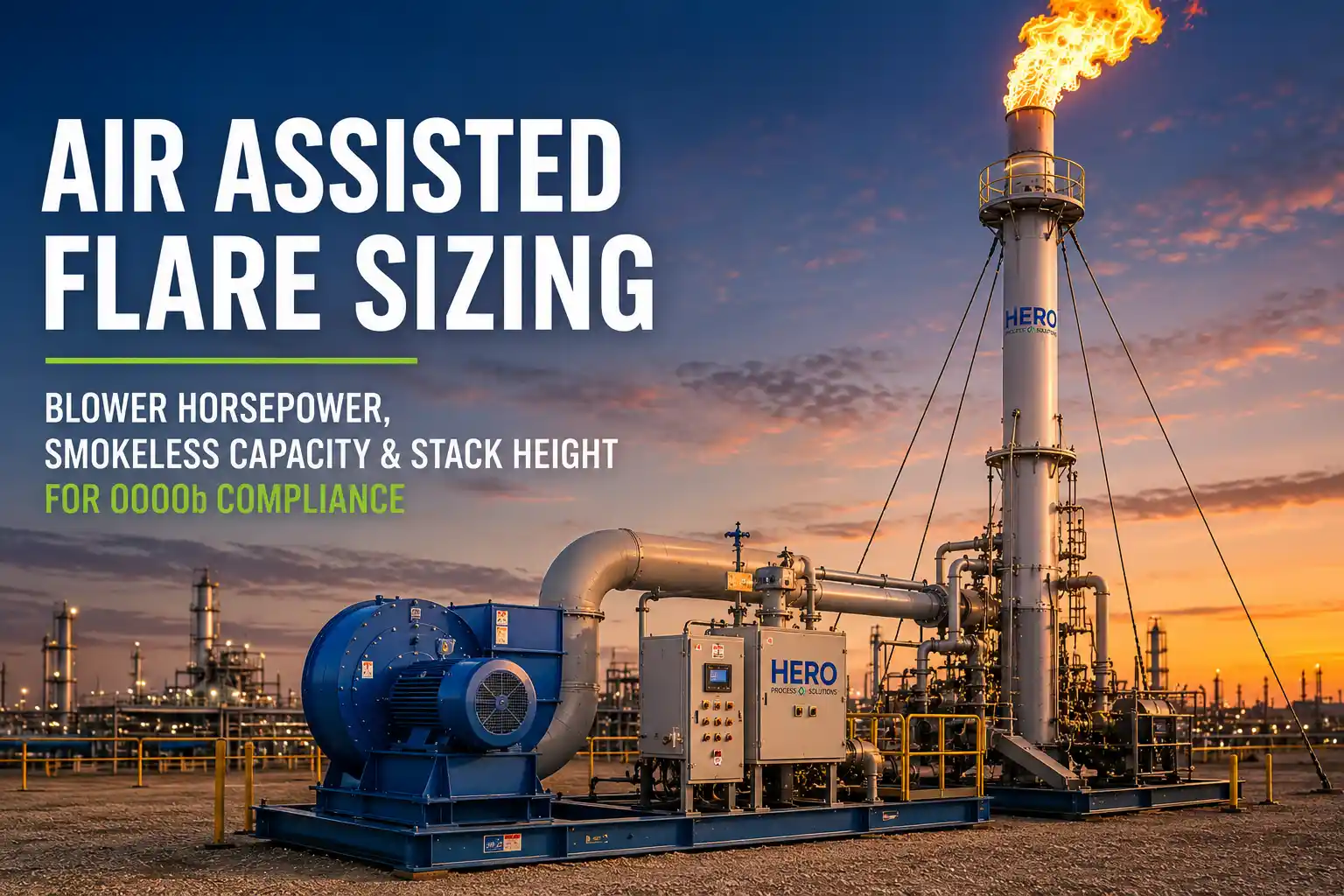
Hero Process Solutions, founded in 2011 and headquartered in Kellyville, Oklahoma with operations in Midland, Texas, manufactures the A+ Series air assisted flare systems line for upstream production, midstream gas processing, refining, and petrochemical applications. This guide walks through the four sizing decisions every air assisted flare specification must answer, and how each ties back to EPA 40 CFR 60 Subpart OOOOb compliance.
DIRECT ANSWER: An air assisted flare is sized using four parameters: peak waste-gas flow rate, smokeless capacity (set by air-to-gas mass ratio of 0.30 to 0.50 lb air per lb gas for typical produced gas), blower horsepower (1 HP to 250 HP depending on tip size), and stack height (set by API Standard 521 thermal radiation and dispersion criteria). A Variable Frequency Drive on the blower is required to maintain 98% Destruction and Removal Efficiency across the full operating range under EPA 40 CFR 60 Subpart OOOOb.
1. How to Define the Design Basis for an Air Assisted Flare
Every air assisted flare sizing exercise starts with the same two inputs: the peak waste-gas flow rate in standard cubic feet per minute and the molecular composition of that gas stream. The peak flow drives the flare tip diameter and the stack height. The composition, specifically the heating value and the percentage of unsaturated hydrocarbons like ethylene and propylene, drives the smokeless capacity requirement and the blower horsepower.
For storage tank vent gas applications, peak flow is typically dominated by working and breathing losses plus emergency relief events. For refinery and gas-processing facilities, peak flow is set by the largest single relief event from a pressure safety valve or a blowdown depressurization scenario. Identify whether the air assisted flare must handle continuous operating gas or emergency-only releases. This single decision drives both blower selection and stack height.
Once the peak flow and composition are locked in, calculate the heat release rate using Heat Release in Btu per hour equals flow rate in scfm multiplied by lower heating value in Btu per scf multiplied by 60. A typical produced-gas stream with a lower heating value around 1,200 Btu per scf at 500 scfm yields a heat release of 36 MMBtu per hour. That number anchors every downstream sizing decision.
2. How to Calculate Smokeless Capacity for an Air Assisted Flare
Smokeless capacity is the maximum waste-gas flow the air assisted flare can burn without producing visible smoke. EPA 40 CFR 60.18 limits flares to no more than five minutes of visible emissions during any consecutive two-hour period, and OOOOb tightens that constraint for affected facilities.
For an air assisted flare, smokeless capacity is a function of three variables: the molecular weight and unsaturation of the waste gas, the air-to-gas mass ratio at the tip, and the turbulence intensity generated by the blower. As a rule of thumb, air assisted flares need approximately 0.30 to 0.50 pounds of combustion air per pound of waste gas to burn smokelessly when the gas contains heavy hydrocarbons. Saturated lighter gases require less, and olefin-rich streams require more.
KEY INSIGHT: The smokeless capacity rating must equal or exceed the maximum expected continuous flow rate, not just the average flow. Designing to the average leaves the air assisted flare operating outside its smokeless window during every peak excursion, which compounds OOOOb visible-emissions compliance risk.
Hero’s A+ Series air assisted flare tips are rated for smokeless flows ranging from several hundred pounds per hour up to over 250,000 lb per hour depending on tip size and blower configuration. Match the design smokeless capacity to your worst-case continuous release scenario and add a 10 to 20 percent margin for composition shifts.
3. How to Select Blower Horsepower for the Air Assisted Flare
Blower horsepower is the single most consequential capital and operating cost decision in the entire flare. Air-assist blowers in the Hero A+ Series range from 1 HP for small storage-tank applications up to 250 HP for large refinery and midstream installations.
The required horsepower is set by three factors: the air mass flow needed at peak smokeless capacity, the static pressure required to deliver that air through the riser and out the tip annulus, and the blower efficiency. A simplified sizing approximation: Blower BHP equals actual cfm multiplied by static pressure drop in inches of water column divided by the product of 6,356 and combined blower-motor efficiency (typically 0.65 to 0.75 for centrifugal blowers in flare service).
For a 500-scfm peak waste-gas flow needing 0.40 lb air per lb gas, the calculation typically lands between 25 and 60 BHP, sized up to the next standard motor frame.
CRITICAL RULE: Every air assisted flare blower must be paired with a Variable Frequency Drive (VFD) to meet EPA 40 CFR 60 Subpart OOOOb. A fixed-speed blower wastes energy at low flow, can blow the flame off the tip during turndown, and fails to hold the 98% DRE standard outside peak design conditions.
Every Hero A+ Series air assisted flare ships with a VFD-controlled blower, and the VFD control loop is calibrated during commissioning to deliver 98% DRE across the full turndown.
4. How to Determine Air Assisted Flare Stack Height
Stack height is set by two independent criteria, and you size for whichever is taller.
The first criterion is thermal radiation. API Standard 521 (Pressure-Relieving and Depressuring Systems) limits ground-level thermal radiation at occupied areas to 1,500 Btu per hour per square foot for emergency releases and lower thresholds for personnel exposure zones. Calculate the radiation flux at distance d as the product of atmospheric transmissivity (typically 0.85), the radiation heat fraction (0.20 to 0.30 for most flare gases), and total heat release, divided by 4 pi d squared.
The second criterion is dispersion. Ground-level concentrations of unburned hydrocarbons, NOx, and CO at the property line must remain below applicable air-quality standards under a worst-case wind condition. Use a Gaussian dispersion model, or AERMOD for permitting-level analysis, to verify the stack height.
Hero’s A+ Series air assisted flare stacks are available from 30 feet to over 100 feet, selected after running both calculations against the site-specific layout.
5. How to Specify Turndown Ratio for Routine Plus Emergency Service
Turndown ratio is the ratio of maximum to minimum stable operating flow. An air assisted flare that must handle both routine 20-scfm tank vent gas and a 5,000-scfm emergency PSV release has a turndown requirement of 250 to 1. Air assisted flares achieve high turndown through VFD blower control plus a stable pilot ignition system holding the flame at very low gas rates.
Design the pilot to handle the minimum expected continuous flow plus a small purge gas allowance. Specify the VFD control range to span the full turndown, typically 10 to 100 percent blower speed. When turndown exceeds 100 to 1, consider a multi-tip or staged configuration so the tip annulus velocity stays within the smokeless window across the full range.
6. Air Assisted Flare vs Other Flare Types: Where Each One Wins
| Flare Type | Best Application | Capacity Range | Key Advantage |
|---|---|---|---|
| Air Assisted (A+ Series) | Continuous or emergency releases needing smokeless, OOOOb-grade combustion | Up to 250,000+ lb/hr smokeless | Active VFD control for 98% DRE at every flow |
| Sonic Flare | Smokeless flaring without auxiliary air or steam | High-pressure waste gas | Coanda effect, no blower OPEX |
| Gas-Assist Flare | Heavy hydrocarbon streams with available fuel gas | Mid-range continuous flow | Lower CAPEX than air-assist |
| Low Flow Flare | Storage tank and well site vent gas | Low continuous flow | Simple design, ideal for upstream |
| Portable Flare | Temporary commissioning or pipeline blowdown | Variable | Trailer-mounted, rapid deploy |
The right selection is application-specific. For continuous service requiring active smokeless control and OOOOb 98% DRE compliance across industrial flare systems, the air assisted flare is typically the right answer.
7. EPA OOOOb Compliance: What the Air Assisted Flare Sizing Spec Must Include
Before finalizing the specification, walk the design back through EPA OOOOb compliance requirements. The air assisted flare must demonstrate 98% DRE on initial performance test and on each annual recertification. The control system must continuously monitor combustion zone presence (via thermocouple or video flame monitor), pilot flame status, and waste-gas flow rate. Records must be retained for five years and reported through EPA’s CEDRI portal.
These requirements affect blower selection (VFD required), instrumentation (continuous monitors), sample-port placement (EPA Method 1 compliance for the annual test), and stack design. Field commissioning support for the initial OOOOb performance test is included with the A+ Series turnkey package.
8. Common Mistakes in Air Assisted Flare Sizing
| Mistake | Why It Hurts Operations / Compliance | Fix |
|---|---|---|
| Sizing smokeless capacity to average flow instead of peak continuous flow | Visible-emission violations under 40 CFR 60.18 at every peak excursion | Size to maximum expected continuous flow plus 10–20% margin |
| Using a fixed-speed blower to save CAPEX | Fails OOOOb 98% DRE at any flow other than peak design | Specify VFD blower with full-range control loop |
| Underestimating peak emergency release | Stack height inadequate for API 521 radiation limit | Run radiation and dispersion calcs at the largest single relief event |
| Ignoring waste-gas composition shift | Air-to-gas ratio falls outside smokeless window when stream changes | Specify control loop tuning for full composition envelope |
| Skipping sample-port placement at design | Cannot run EPA Method 1-compliant annual performance test | Locate ports per Method 1 during fabrication, not after |
| Forgetting the pilot turndown spec | Flame-out during low-flow operation, triggers OOOOb deviation | Specify pilot for minimum continuous flow plus purge allowance |
Frequently Asked Questions
What is the typical air-to-gas mass ratio for sizing an air assisted flare?
For typical produced gas streams in oil and gas applications, the air-to-gas mass ratio falls between 0.30 and 0.50 pounds of combustion air per pound of waste gas. Olefin-rich streams (with significant ethylene or propylene content) require ratios at the upper end of that range or above. Always confirm the ratio against the specific gas composition before locking in blower horsepower.
How large should the blower be on an air assisted flare?
Blower size is set by the air mass flow required at peak smokeless capacity, the static pressure drop through the riser and tip annulus, and the combined blower-motor efficiency (typically 0.65 to 0.75). Hero’s A+ Series air assisted flare blowers range from 1 HP for small storage-tank applications to 250 HP for large refinery and midstream installations.
Do I need a Variable Frequency Drive on the blower for OOOOb compliance?
Yes. EPA 40 CFR 60 Subpart OOOOb requires 98% Destruction and Removal Efficiency across the full operating range, not just at peak design flow. A fixed-speed blower over-supplies air during normal turndown and cannot hold 98% DRE. Every Hero A+ Series air assisted flare ships with a VFD-controlled blower for this reason.
How tall does an air assisted flare stack need to be?
Stack height is set by the more conservative of two criteria: API Standard 521 thermal radiation limits at occupied areas (typically 1,500 Btu per hour per square foot for emergency releases) and Gaussian dispersion modeling for ground-level concentrations of unburned hydrocarbons, NOx, and CO. Hero’s A+ Series stacks range from 30 feet to over 100 feet depending on site-specific calculations.
What is the turndown ratio of an air assisted flare?
Turndown ratio is the ratio of maximum stable to minimum stable operating flow. Air assisted flares routinely achieve turndowns of 100 to 1 or higher through VFD blower control plus a stable pilot system. Service that combines low routine flow with large emergency relief releases can require turndowns of 250 to 1, sometimes achieved through staged-tip configurations.
What sizing data does Hero Process Solutions need to quote an air assisted flare?
Hero typically asks for peak waste-gas flow rate (scfm), gas composition (with heating value), continuous vs emergency-only service, available utility power, site layout for radiation and dispersion modeling, and the applicable EPA OOOOb / OOOOc compliance status. With those inputs, the A+ Series package can be sized and quoted including stack, tip, VFD blower, pilot, ignition, monitoring, and control system.