OIL & GAS EQUIPMENT | Updated May 2026 | 7 min read
What You’ll Learn in This Guide
- How to define the design basis for a low flow flare on storage tank vent gas service
- How to calculate working and breathing losses from API 2517 and AP-42 emission factors
- How to size for flash gas during fill events and pressure swings
- Why 40 CFR 60 Subpart Kb and OOOOb storage tank rules drive the design
- How to specify battery or solar-powered spark ignition for unmanned well-site service
- How to integrate a low flow flare into a multi-tank battery without backflow risk
- Common low flow flare sizing mistakes and how to avoid them
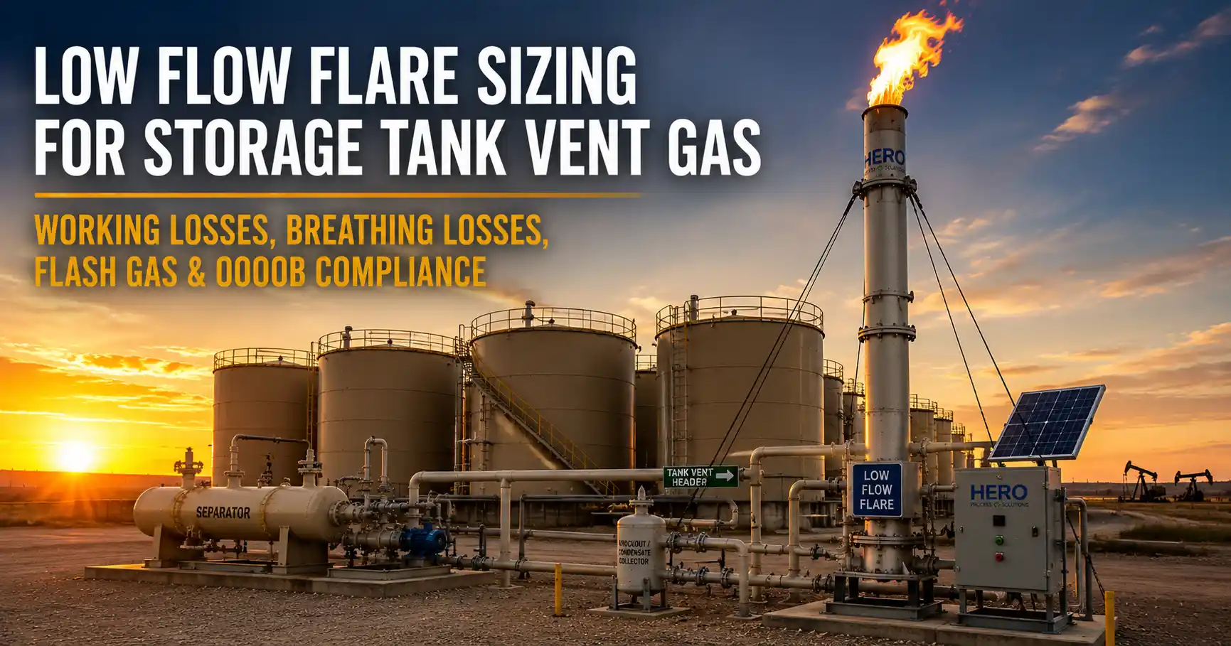
A low flow flare exists for one specific job: combust the intermittent, low-volume vent gas from upstream storage tanks, well-site separators, and small process equipment that cannot economically justify a vapor recovery unit. The sizing math is structurally different from a refinery or midstream flare because the flow is not a steady mass rate to size for — it is a pattern of working losses, breathing losses, flash gas during fill cycles, and occasional larger excursions. Getting the design right depends on understanding the source emissions profile, not just the peak flow number.
Hero Process Solutions, founded in 2011 and headquartered in Kellyville, Oklahoma with operations in Midland, Texas, manufactures low flow flare systems with battery and solar-powered direct spark ignition for unmanned well sites and small tank batteries. This guide walks through the sizing methodology and explains how the design connects to EPA 40 CFR 60 storage tank standards.
DIRECT ANSWER: A low flow flare is sized for the actual upstream emissions profile — working losses (vapor displaced during tank fill), breathing losses (vapor expansion from diurnal temperature changes), and flash gas (vapor liberated when produced liquid drops from separator pressure to atmospheric tank pressure). Working and breathing losses are calculated using API 2517 and EPA AP-42 emission factors; flash gas is calculated from a flash calculation on the separator outlet liquid. The flare must handle the combined peak from all three sources, with margin for production swings, and ignite reliably under unmanned battery/solar power across years of intermittent service.
1. How to Define the Design Basis for a Low Flow Flare
Storage tank vent gas service has a unique flow profile. The flare may sit at near-zero flow for hours during stable operation, then see a spike during a tank fill event, then return to breathing-loss flow for the rest of the day. The peak flow is not the design basis by itself — the design basis is the combined emissions inventory, the peak event, and the duty cycle of the flare across the year.
Three inputs anchor the sizing exercise. First, the tank inventory and production rate — number of tanks, tank size, fill cycle frequency, daily liquid throughput. Second, the produced liquid composition — API gravity, gas-oil ratio (GOR), saturation pressure, which together determine flash gas potential. Third, the climate and orientation — diurnal temperature swing, tank color and shell type (fixed roof vs internal floating roof), which together determine breathing losses.
For most upstream tank batteries, peak vent gas flow falls in the 50 SCFM to 500 SCFM range, with annual average flow well below the peak. The low flow flare must handle the peak with margin while remaining stable at much lower routine flows.
2. How to Calculate Working and Breathing Losses
Working losses are the vapors displaced from the tank vapor space when liquid is added — fill from a truck, transfer from a separator, or any other inflow. The vapor volume displaced equals the liquid volume added, and the mass of that displaced vapor depends on vapor pressure and composition.
EPA AP-42 Chapter 7 gives the standard equations for working loss emissions from fixed-roof tanks. For typical crude oil at moderate Reid vapor pressure (RVP 5 to 9 psia), working loss is approximately 0.5 to 2 pounds of vapor per barrel of liquid added. A tank battery receiving 1,000 BPD of production generates working loss flow on the order of 5 to 25 SCFM averaged across the day, with brief spikes during active fill events of 50 to 500 SCFM.
Breathing losses are the vapors expelled when tank vapor space pressure rises with daytime heating and contracts overnight. API 2517 and AP-42 give the breathing loss equations for fixed-roof tanks; the dominant variables are diurnal temperature swing, vapor pressure of the stored liquid, tank shell color, and tank dimensions. For a typical upstream crude tank, breathing loss runs 0.1 to 1 SCFM continuous as a 24-hour average.
KEY INSIGHT: Working loss spikes during active fill events are the controlling peak flow for low flow flare tip sizing, not the average daily emissions. Size the tip to handle the largest single fill event the battery can produce, then verify pilot and ignition reliability across the much lower routine flow regime.
3. How to Size for Flash Gas During Separator Production
Flash gas is the third and often largest emission component on upstream tank batteries. When produced liquid leaves the separator (at operating pressure of 50 to 200 psig) and enters the storage tank (at atmospheric pressure), the dissolved gas flashes out of solution. The flash gas rate depends on the gas-oil ratio at separator conditions and the pressure differential between separator and tank.
Flash gas is calculated using a flash equation on the separator outlet liquid composition or, for routine engineering work, the GPSA Engineering Data Book flash factor correlations. For typical crude oil produced through a 100 psig separator, flash gas at the tank inlet is on the order of 5 to 50 SCF per barrel of liquid throughput. A 1,000 BPD battery with that flash factor produces 5,000 to 50,000 SCF per day of flash gas, or roughly 4 to 35 SCFM on an averaged basis. During active production, instantaneous flash rates run several times higher.
Flash gas plus working loss plus breathing loss combined gives the total vent gas flow the low flow flare must handle. The flare tip must be sized for the combined peak, not the sum of individual averages.
4. EPA Storage Tank Standards Driving the Design
Two EPA regulations directly drive the low flow flare specification for storage tank service. 40 CFR 60 Subpart Kb (Standards of Performance for Volatile Organic Liquid Storage Vessels) applies to larger tanks meeting specified capacity and vapor pressure thresholds; it typically requires emission controls achieving 95% VOC reduction. 40 CFR 60 Subpart OOOOb applies to storage vessels on affected oil and gas facilities and requires 95% VOC reduction by control device (which can be a low flow flare) for tanks above the rule’s vapor pressure and throughput thresholds.
For low flow flares used as Subpart OOOOb control devices, the flare must demonstrate 98% destruction efficiency on initial and annual performance tests, continuously monitor pilot flame status, and maintain records for five years with CEDRI reporting. Visit our EPA OOOOb compliance resource for the full requirements.
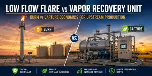
The combination of these rules is why every upstream operator now needs a control strategy for storage tank vent gas. The low flow flare is one of the two standard answers (the other being a vapor recovery unit, covered in our separate burn-vs-capture analysis).
5. How to Specify Battery/Solar Spark Ignition for Unmanned Service
Low flow flares are typically installed at unmanned well sites without grid power. The ignition system must run on battery and solar for years of continuous service, ignite vent gas reliably whenever flow arrives, and survive weather extremes that the site experiences.
Hero’s low flow flares use a battery and solar-powered direct spark ignition system that produces a spark at the flare tip every three seconds regardless of whether waste gas flow is present. This continuous-spark architecture eliminates the reliability concern of a continuously lit pilot at an unmanned site — there is no pilot flame to lose, no pilot fuel to manage, no pilot relight sequence to complete before the main flow can ignite. When vent gas arrives at the tip, the next 3-second spark ignites it.
For higher-reliability OOOOb applications, the ignition system can be paired with a flame ionization detector to confirm combustion when waste gas flow is present, with the detection signal logged for compliance records. The pilot ignition system page covers the alternative continuous-pilot architectures used on continuous-service flares.
6. How to Integrate a Low Flow Flare into a Multi-Tank Battery
Most upstream tank batteries have multiple tanks manifolded together. Integrating a single low flow flare across the battery requires four design checks.
First, vent header sizing — the manifold connecting all tank vapor spaces to the flare must be sized for combined peak flow from all tanks during simultaneous fill events, with pressure drop low enough to keep each tank vapor space at design pressure during normal operation.
Second, backflow protection — a single flare drawing vapor from a manifolded battery must not pull a vacuum on any one tank during the brief moment when no fill is active. Vacuum breakers or pressure-vacuum relief valves on each tank prevent tank collapse.
Third, flame arrestor placement — the vent header should include a flame arrestor between the tank battery and the flare to prevent flame propagation back into the tank vapor space during ignition events.
Fourth, knockout drum sizing — produced liquid carryover from the tank battery to the flare must be eliminated by a properly sized knockout drum upstream of the flare base. Hero’s liquid knockout systems are sized for the specific battery configuration.
7. Low Flow Flare vs Other Flare Types
| Flare Type | Typical Service | Capacity Range | When Low Flow Flare Wins |
|---|---|---|---|
| Low Flow Flare | Storage tank vent, well site separator, small process equipment | 10 SCFM to ~500 SCFM peak | Unmanned upstream service, intermittent flow, battery/solar ignition |
| Gas Assisted Flare | Continuous smokeless service, heavier hydrocarbons | Up to 200,000 SCFD continuous | Steady continuous flow with fuel gas available |
| Air Assisted Flare | Continuous smokeless, low pressure, electric available | Up to 250,000+ lb/hr | Mid-scale midstream or refining with utilities |
| Utility Flare | Emergency relief only | Up to 1,000,000+ lb/hr peak | Worst-case API 521 contingency, not routine flow |
| Vapor Combustor | Continuous enclosed combustion of vapor | Low to moderate continuous flow | Visual screening of flame required, denser site layout |
Across the full industrial flare systems portfolio, the low flow flare is the standard answer for upstream well sites and small tank batteries with intermittent low-volume vent gas service.
8. Common Low Flow Flare Sizing Mistakes
| Mistake | Why It Hurts | Fix |
|---|---|---|
| Sizing the tip to average daily emissions instead of peak fill event | Tip undersized during active fill, flames out or fails 95% control | Size tip to combined peak (working + flash) at largest fill event |
| Ignoring flash gas because GOR data is incomplete | Flash gas often dominates the emissions inventory | Run flash calculation on separator outlet liquid; do not skip |
| Specifying continuous pilot at unmanned site | Pilot loss is undetected, no flow combustion when needed | Use direct spark ignition with 3-second cycle for unmanned service |
| No flame arrestor on the vent header | Risk of flame propagation back into tank vapor space | Specify flame arrestor between battery manifold and flare |
| Missing knockout drum upstream of flare base | Liquid carryover damages tip and creates ignition risk | Specify knockout drum sized for worst-case liquid carryover |
| Skipping OOOOb classification check | Tank battery may be subject to Kb and OOOOb without operator awareness | Run classification check during design; document control device path |
Frequently Asked Questions
What is a low flow flare designed for?
A low flow flare is designed for intermittent, low-volume vent gas from upstream storage tanks, well-site separators, and small process equipment that cannot economically justify a vapor recovery unit. Typical capacity range is 10 SCFM to 500 SCFM peak, with much lower routine flow. The flare runs on battery and solar power at unmanned well sites with direct spark ignition that fires every three seconds.
How is storage tank vent gas calculated for low flow flare sizing?
Storage tank vent gas comes from three sources: working losses (vapor displaced during fill, calculated via EPA AP-42 Chapter 7), breathing losses (diurnal vapor expansion, calculated via API 2517), and flash gas (vapor liberated when separator liquid drops to tank pressure, calculated from flash equations or GPSA correlations). The low flow flare must handle the combined peak from all three, not the sum of averages.
Does a low flow flare need to meet EPA OOOOb 98% DRE?
Yes, when the low flow flare is used as a control device on a storage vessel that meets the 40 CFR 60 Subpart OOOOb applicability thresholds. The flare must demonstrate 98% destruction efficiency on initial and annual performance tests, continuously monitor pilot or ignition status, and maintain records for five years with CEDRI reporting. Subpart Kb may also apply to larger tanks above its capacity and vapor pressure thresholds.
How does the battery/solar spark ignition work?
The Hero low flow flare ignition system uses battery and solar power to produce a spark at the flare tip every three seconds, regardless of whether waste gas flow is present. When vent gas arrives at the tip — from a fill event, flash, or breathing loss spike — the next 3-second spark ignites it. The continuous-spark architecture eliminates pilot reliability concerns at unmanned sites.
Can a single low flow flare serve a multi-tank battery?
Yes, with proper integration design. The vent header connecting all tank vapor spaces must be sized for combined peak fill flow, vacuum breakers on each tank prevent tank collapse, a flame arrestor on the header prevents flame propagation back to the tanks, and a liquid knockout drum upstream of the flare base eliminates carryover. With those four design elements, one low flow flare handles the entire battery.
What data does Hero Process Solutions need to size a low flow flare?
Hero typically asks for tank count and size, daily liquid throughput, produced liquid composition (API gravity, gas-oil ratio, RVP), separator operating pressure and temperature, ambient climate and diurnal swing, site location and grid power availability, and OOOOb / Kb classification status. With those inputs, the low flow flare can be sized including tip, stack, battery/solar ignition, knockout drum, and vent header.