OIL & GAS EQUIPMENT | Updated May 2025 | 7 min read
• How an A-frame BTEX condenser is designed and how the geometry affects performance
• Why A-frame configurations are preferred for certain upstream oil and gas applications
• Key operational advantages of the A-frame design over vertical condenser units
• Which regulatory requirements the A-frame system addresses at production sites
• How to integrate an A-frame BTEX unit with a tank battery vapor control train
• Maintenance access advantages of the A-frame design in field environments
• Hero Process Solutions’ A-frame BTEX system specifications and service support
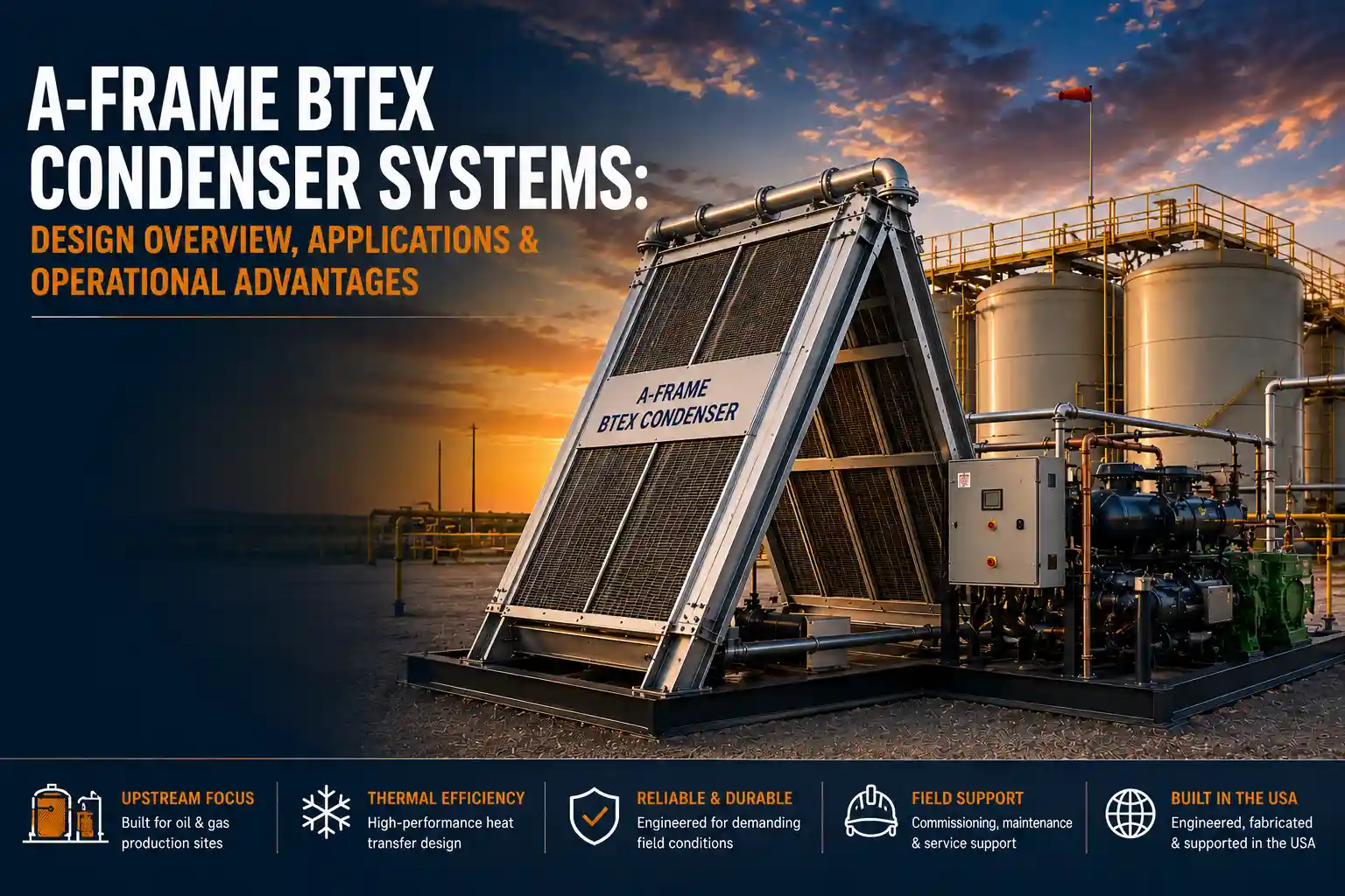
A-frame BTEX condenser systems are the preferred vapor control configuration for upstream oil and gas tank batteries where BTEX compounds — benzene, toluene, ethylbenzene, and xylene — must be condensed out of the vent gas stream. The inclined heat exchanger geometry that defines the A-frame design gives it operational advantages in condensate drainage, heat exchanger access, and installed footprint that make it a practical choice for production sites with limited civil infrastructure. Under EPA NESHAP 40 CFR Part 63, Subpart HH and state benzene control requirements in Texas and Oklahoma, BTEX condensers are not optional at facilities that exceed major HAP source thresholds.
Hero Process Solutions, founded in 2011 and headquartered in Kellyville, OK, engineers and fabricates A-frame BTEX condenser systems for upstream and midstream oil and gas operations. The company provides direct field services support for commissioning and maintenance from its Midland, TX operations, serving Permian Basin production sites with both A-frame and vertical condenser configurations.
An A-frame BTEX condenser system is a heat exchanger in which the condensing surface is arranged in an inverted-V (A-frame) geometry that allows condensate to drain by gravity to a bottom collection trough. Tank vent gas flows through the heat exchanger, BTEX compounds condense on the cooled surfaces, and the liquid drains to a collection sump from which it is returned to the product stream. The A-frame design offers a low-height profile, easy surface access for cleaning, and efficient condensate drainage without a separate separator vessel.
1. A-Frame Design Geometry: How It Works
The A-frame configuration takes its name from the shape of the heat exchanger assembly when viewed from the end. Two inclined heat exchanger panel sections meet at the top of the unit, forming an inverted V or A-shape. Warm tank vent gas enters the A-frame condenser and flows across the inclined heat exchanger surfaces. As the gas contacts the chilled surface, its temperature drops below the dew point of the BTEX compounds and heavier hydrocarbons. These components condense on the surface and drain downward by gravity along the inclined tube or plate surface toward the collection trough at the bottom.
Because condensate drains continuously by gravity to the trough — rather than accumulating on horizontal surfaces — the heat exchanger stays relatively clean and the condensate collection is passive (no pump required for drainage under gravity conditions). The cooling medium inside the A-frame is either a refrigerant in a vapor-compression refrigeration cycle or a chilled glycol-water solution. Target outlet temperatures of 0 to 40 degrees F are typical for standard NESHAP compliance; for deep BTEX removal, outlet temperatures of minus 20 to minus 40 degrees F may be specified.
2. Operational Advantages of the A-Frame Configuration
Low-Profile Footprint
The A-frame spreads horizontally rather than building height. This matters at production sites where overhead clearances are limited and where a tall vertical vessel would require additional structural support or wind bracing. A-frame units typically have a height of 6 to 10 feet for standard capacity ranges, compared to a vertical unit of similar capacity that may stand 12 to 18 feet.
Gravity Condensate Drainage
The inclined surface geometry drains condensate continuously without liquid accumulation on the heat exchanger surfaces. On a horizontal or vertical tube bundle, condensate can pool on surfaces and reduce heat transfer efficiency over time. The A-frame geometry eliminates this pooling concern as a design feature rather than a maintenance task.
Open Access for Heat Exchanger Cleaning
In production environments, the incoming vent gas carries mist droplets, light hydrocarbons, and occasionally fine particulates from the tank. On an A-frame unit, the heat exchanger surfaces are accessible from the exterior of the unit without opening a pressure vessel. A field technician can clean the surfaces with a pressure washer or brush without removing internal components or breaking vessel flanges.
The gravity drainage feature of the A-frame design has a direct effect on heat transfer performance over the life of the unit. Heat exchanger surfaces covered with liquid condensate film have lower effective heat transfer coefficients than dry surfaces. Continuous gravity drainage from the inclined A-frame panels maintains cleaner surfaces and more consistent thermal performance throughout the operating period between scheduled maintenance events.
3. Applications Where A-Frame BTEX Systems Excel
The most common application is the crude oil tank battery at an upstream production site. High-API crude releases significant aromatic content into the tank vapor space, particularly in summer when ambient temperatures drive high volatilization rates. An A-frame unit installed in the vent header serves multiple tanks simultaneously and handles the combined thermal breathing and working loss vapor volumes.
Condensate storage tanks carry even higher BTEX concentrations than crude tanks because condensate is rich in the C5 to C8 hydrocarbon range where aromatics concentrate. The A-frame’s low-height profile and horizontal geometry also make it efficient to mount on a skid or trailer for mobile deployment, moving between production sites as BTEX control needs shift across a field program. When a production site’s regulatory classification changes, an A-frame BTEX condenser can be retrofitted upstream of an existing vapor recovery system with minimal piping modification.
4. Regulatory Compliance: What the A-Frame System Addresses
For production facilities classified as major HAP sources (benzene emissions at or above 10 tons per year, or combined HAPs at or above 25 tons per year), NESHAP 40 CFR Part 63, Subpart HH requires HAP emission control from storage tanks. An A-frame BTEX condenser upstream of the combustor or VRU provides the required emission reduction. The OOOOb standard requires VOC control from storage vessels at affected facilities above applicable throughput thresholds; an A-frame BTEX condenser reduces VOC emissions from the tank vent stream, contributing to OOOOb compliance.
The A-frame BTEX condenser must be sized for the maximum vapor generation rate at peak summer conditions, not average annual emission rates. Tank breathing losses increase substantially in summer when ambient temperature drives high volatilization. A condenser sized only for cool season vapor rates will be insufficient in summer and will not achieve the required BTEX removal efficiency under peak conditions.
5. Maintenance and Field Service Considerations
Routine maintenance items include heat exchanger surface inspection and cleaning (quarterly or semi-annually depending on vapor cleanliness), condensate return line inspection for flow restrictions or scale buildup, and refrigeration system service (refrigerant charge check, compressor oil level, filter drier replacement). Hero Process Solutions provides aftermarket support including replacement components and refrigerant service for A-frame units manufactured by Hero PS, with field service coverage from Kellyville, OK and Midland, TX.
Common Mistakes to Avoid
| Mistake | Why It Hurts | Fix |
|---|---|---|
| Sizing for cool season vapor rates | Undersized for summer peak; compliance failure in high-temperature months | Size for maximum daily ambient temperature and worst-case thermal breathing losses |
| No condensate return line isolation valve | Cannot isolate the return during maintenance | Install isolation valves at the tank connection and at the condenser drain |
| Neglecting heat exchanger surface cleaning | Scale and deposit buildup reduces heat transfer; BTEX removal declines | Schedule quarterly inspection; clean surfaces with approved solvent or pressure wash |
| Operating with low refrigerant charge | Reduced cooling capacity; outlet temperature too high | Include refrigerant charge verification in semi-annual maintenance program |
| Installing the unit too close to tank vents | Warm air from the tank vent header pre-heats the condenser exterior | Provide adequate separation between the tank vent header and the condenser panels |
Article Summary
- A-frame BTEX condenser systems use an inclined heat exchanger geometry that allows condensate to drain by gravity to a bottom collection trough without a separate separator vessel.
- The low-height profile of the A-frame design is an advantage at production sites with overhead clearance restrictions or space limitations.
- Open access to the heat exchanger surface simplifies field cleaning without breaking pressure vessel connections.
- The A-frame configuration scales well for large multi-tank battery applications by widening the panel area without adding height.
- Applications include crude oil tank batteries, condensate storage tanks, and mobile skid-mounted BTEX control systems.
- NESHAP 40 CFR Part 63, Subpart HH drives BTEX control requirements at major HAP source facilities; OOOOb addresses VOC from storage vessels.
- A-frame systems must be sized for peak summer vapor generation rates, not average annual emission data.
- Hero Process Solutions provides A-frame BTEX systems and field service support from Kellyville, OK and Midland, TX.
Frequently Asked Questions
What is an A-frame BTEX condenser system?
An A-frame BTEX condenser system is a heat exchanger with an inclined panel geometry (resembling an inverted V or A-shape) used to condense benzene, toluene, ethylbenzene, and xylene from oil and gas tank vent gas. The inclined surface allows condensate to drain by gravity to a bottom collection trough, avoiding liquid accumulation on the heat exchanger surfaces. The system chills incoming vapor below the BTEX dew point using a refrigerant or glycol cooling circuit.
What are the advantages of an A-frame BTEX unit over a vertical condenser?
A-frame units have a lower height profile (important where overhead clearance is limited), allow gravity drainage of condensate without requiring a separate condensate separator, and provide easier access to the heat exchanger surface for cleaning in the field. Vertical condensers have a smaller ground footprint and are better suited for high-pressure service. The choice depends on site layout, pressure requirements, and whether the unit needs to be mobile.
What size A-frame BTEX condenser do I need for a tank battery?
Sizing depends on your total vapor generation rate from the tank battery (in SCFH), inlet gas temperature, BTEX concentration in the vent gas, and the required outlet BTEX concentration or removal efficiency from your permit. Hero Process Solutions’ engineering team can perform a sizing calculation with your tank emission data or assist with a vent gas sampling program to get the data needed for accurate sizing.
How often does an A-frame BTEX condenser need maintenance?
Routine maintenance intervals depend on the cleanliness of the incoming vapor and the operating temperature of the unit. At a minimum, quarterly inspections of the heat exchanger surface, condensate return line, and refrigeration system are recommended. Full refrigeration system service (refrigerant charge, compressor oil, filter drier) is typically annual. Hero Process Solutions’ field services team can provide scheduled maintenance under a service agreement.
Does an A-frame BTEX condenser qualify as a HAP control device under NESHAP Subpart HH?
An A-frame BTEX condenser can qualify as a HAP control device under NESHAP Subpart HH if it achieves the required BTEX removal efficiency specified in your permit. The unit must be designed and documented to meet the required control efficiency. Confirm the specific performance requirement with your permitting consultant before finalizing the equipment specification.