

OIL & GAS EQUIPMENT | Updated May 2026 | 8 min read
What You’ll Learn in This Guide
- The mechanical difference between single-point and multi-point staged sonic flare configurations
- How turndown ratio drives the staging decision
- When single-point sonic flares are the right answer despite the turndown limitation
- How multi-point staged designs achieve 50:1 or higher turndown without smoke
- The control logic and valve sequencing that makes staging work
- How OOOOb 98% DRE requirements interact with the staging choice
- Common selection mistakes and how to specify the right configuration
A sonic flare achieves smokeless combustion through choked-flow exit velocity at the tip, which requires sustained upstream pressure. The single biggest engineering constraint in sonic flare design is what happens when waste-gas flow drops below the level that maintains choked conditions the tip un-chokes, exit velocity falls, and the smokeless behavior disappears. Single-point sonic flare configurations live with this turndown limitation. Multi-point staged configurations engineer around it by bringing multiple tips of different sizes on line as flow rises. The choice between the two is one of the most consequential engineering decisions in any sonic flare project.
Hero Process Solutions, founded in 2011 and headquartered in Kellyville, Oklahoma with operations in Midland, Texas, manufactures sonic flares with Coanda-profile tips in both single-point and multi-point staged configurations for upstream production, midstream gas processing, and refining customers. This guide walks through the engineering trade-offs so project teams can specify the right configuration for the actual operating envelope.
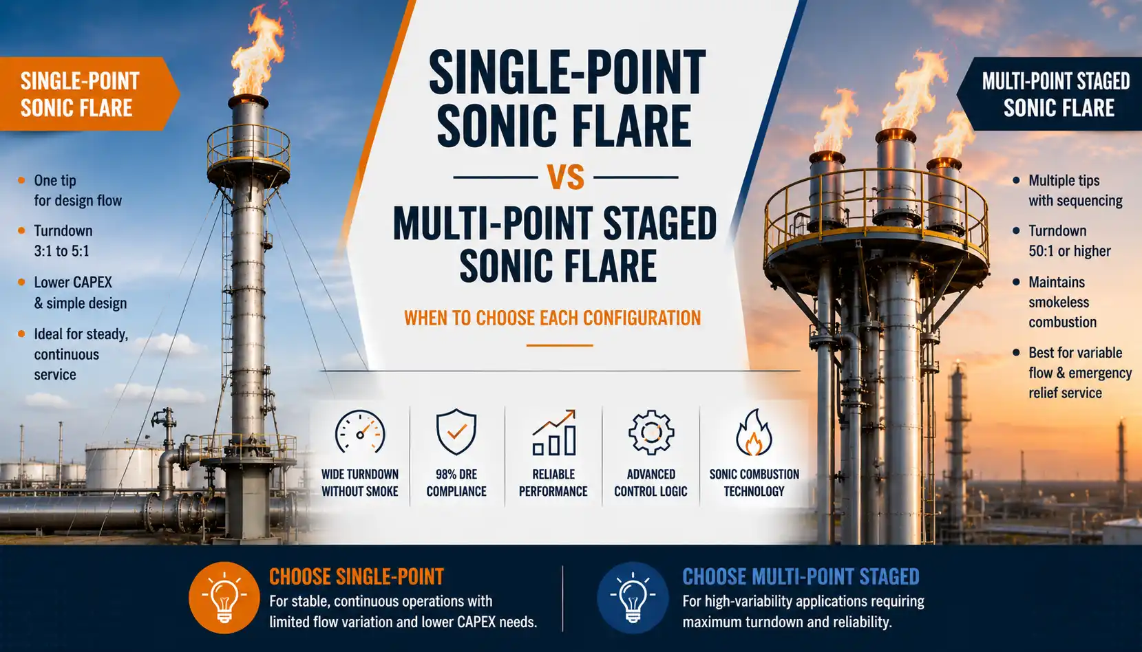
DIRECT ANSWER: A single-point sonic flare uses one tip sized for the design flow with practical turndown of 3:1 to 5:1 adequate for relatively stable continuous service but unsuitable for wide-turndown applications. A multi-point staged sonic flare uses multiple tips of different sizes on a manifold with sequencing valves that bring tips on line as waste-gas flow rises, achieving turndowns of 50:1 or higher without losing smokeless combustion or 98% DRE compliance. Choose single-point for steady continuous service with limited flow variation; choose multi-point staged for high-variability service combining low routine flow with periodic excursions.
1. The Mechanical Difference Between Single-Point and Multi-Point Sonic Flares
A single-point sonic flare uses one tip on top of one stack. The tip throat is sized for the design peak flow rate using the choked-flow mass equation. At peak flow, the gas exits at sonic velocity through the tip and combustion is smokeless. As flow drops below the level that maintains the critical pressure ratio across the tip, the tip un-chokes and the smokeless behavior degrades.
A multi-point staged sonic flare uses several tips of different sizes mounted on a common manifold, typically arranged in a circle or linear array. Each tip has its own sequencing valve. At low waste-gas flow, only the smallest tip is open that tip operates at choked flow because the entire low flow is concentrated through it. As flow rises, intermediate-size tips are brought on line in sequence. At peak flow, all tips are open with the largest tips carrying the bulk of the load.
The staging approach maintains choked-flow conditions across the entire operating range by always concentrating the actual flow through tips small enough to maintain pressure ratio. The result is smokeless combustion from routine low flow through peak emergency relief.
2. Turndown Ratio Drives the Staging Decision
Turndown ratio is the ratio of maximum stable to minimum stable operating flow. The required turndown for a specific application is set by the operational profile of the waste-gas source.
For relatively steady continuous service a midstream gas processing facility with stable vent gas flow turndown requirements may be only 3:1 to 5:1 across normal operating variation. A single-point sonic flare handles this turndown range within its choked-flow envelope.
For variable service combining low routine flow with periodic excursions a refinery flare handling both routine flash gas (20 scfm) and emergency PSV relief events (5,000 scfm) turndown requirements reach 250:1 or higher. Single-point sonic flares cannot maintain choked conditions across this range. Multi-point staged configurations are the only sonic flare answer.
KEY INSIGHT: The first question in any sonic flare project is what turndown ratio the application requires. Below 5:1, single-point usually wins on CAPEX. Above 100:1, multi-point staged is the only option that maintains smokeless combustion across the range. Between 5:1 and 100:1, both options work and the choice depends on CAPEX vs control complexity preferences.
3. When Single-Point Sonic Flares Win
Single-point sonic flare configurations win on five specific application categories.
Steady continuous service with limited flow variation. A midstream gas plant with relatively constant vent gas flow within a 3:1 to 5:1 turndown window works well with single-point sonic flare design.
Lower CAPEX projects. Single tip plus one stack is mechanically simpler than multi-tip manifold with sequencing valves. CAPEX is typically 20% to 40% lower than multi-point staged at equivalent peak capacity.
Less complex control system. Single-point sonic flares need pressure monitoring and pilot status that’s effectively the entire control system. Multi-point staged systems require flow measurement, valve sequencing logic, and combustion-zone feedback across all tips.
Routine maintenance simplicity. One tip to inspect, one tip to replace at 5-year overhaul. Multi-tip systems have more components on the maintenance schedule.
Service profiles where smokeless operation at very low flow is not required. If the operator can tolerate occasional smoke during sub-choke conditions (rare in OOOOb-affected service), single-point is acceptable.
4. When Multi-Point Staged Sonic Flares Win
Multi-point staged configurations win whenever smokeless combustion must be maintained across wide turndown.
Combined routine plus emergency relief service. A refinery flare handling both routine 50 scfm flash gas and emergency 50,000 scfm PSV relief has 1,000:1 turndown that only staged configurations can deliver smokelessly.
OOOOb-affected facilities requiring continuous 98% DRE. Sub-choke operation drops DRE below the 98% threshold and triggers OOOOb deviation events. Staged configurations maintain choked-flow conditions across the operating range and preserve 98% DRE compliance.
Variable composition service. Inlet composition shifts that move the critical pressure ratio threshold affect single-point operation differently than staged operation. Staged designs tolerate composition variation better because the smaller tips have more design margin.
High-stakes refinery and petrochemical service. The combination of variable load, OOOOb (or equivalent) compliance requirements, and operational visibility makes the multi-point staged investment defensible despite higher CAPEX.
5. Control Logic and Valve Sequencing
Multi-point staged sonic flare control logic uses three inputs: vent-gas flow rate at the manifold inlet, manifold pressure, and combustion-zone status from each operating tip. Three outputs drive the staging behavior: open/close commands to each sequencing valve, pilot status verification, and alarm logic for off-design conditions.
At low flow, only the smallest tip is open. The control system monitors inlet flow and manifold pressure. When flow rises above the smallest tip’s choked-flow capacity (signaled by pressure rising above setpoint), the next-larger tip’s valve opens. This continues through the tip array as flow grows. On flow decline, valves close in reverse order to drop unused tips out of service.
Hysteresis between open and close thresholds prevents valve cycling at flow rates near the staging boundary. Typical hysteresis is 20% to 30% of the staging threshold large enough to prevent oscillation, small enough to track real flow changes responsively.
6. OOOOb 98% DRE Across the Staging Range
EPA 40 CFR 60 Subpart OOOOb requires 98% Destruction and Removal Efficiency on flares used as control devices at affected facilities. The standard must be maintained across the full operating range, not just at peak design flow. Visit our EPA OOOOb compliance resource for the complete requirements.
For single-point sonic flares, 98% DRE is maintained as long as the tip remains choked. When flow drops below the choking threshold, exit velocity falls and DRE typically drops below 98%. Single-point sonic flares are therefore restricted to applications where the entire operating range stays within the choked-flow window.
Multi-point staged sonic flares maintain 98% DRE across the full operating range because the active tips at any flow rate are always choked. The control system ensures that flow is concentrated through enough tips to maintain choked conditions but not so many that any tip sees flow below its lower limit. This is the engineering rationale for the staged architecture on OOOOb-affected service.
7. CAPEX Comparison Single-Point vs Multi-Point
| Component | Single-Point | Multi-Point Staged |
|---|---|---|
| Tip count | 1 | 3 to 8 typical |
| Sequencing valves | None | 1 per tip (excluding smallest) |
| Manifold | None (direct stack) | Required to distribute flow across tips |
| Control logic complexity | Low (pressure, pilot) | High (flow, pressure, valve sequencing) |
| Combustion-zone monitoring | Single point | Per-tip or aggregated |
| Typical CAPEX | Baseline | 20% to 50% premium over single-point |
| Service life | Comparable (longer tip life on single) | Comparable (more tips but lower per-tip load) |
The CAPEX premium for multi-point staged is real but often paid back through OOOOb compliance certainty, reduced operational risk, and avoided permit complications. For OOOOb-affected facilities requiring smokeless operation across wide turndown, the staged investment is increasingly the default rather than the exception.
8. Common Sonic Flare Configuration Selection Mistakes
| Mistake | Why It Hurts | Fix |
|---|---|---|
| Specifying single-point for wide-turndown service | Tip un-chokes during low flow, smokes, fails 98% DRE | Specify multi-point staged for turndowns above 5:1 |
| Specifying multi-point for steady continuous service | CAPEX premium not justified by operating profile | Single-point handles 3:1 to 5:1 turndown well |
| Ignoring combustion-zone monitoring per tip on staged designs | Cannot prove OOOOb compliance on individual tip basis | Specify per-tip combustion-zone monitoring |
| Setting valve sequencing thresholds without hysteresis | Valves cycle at flow rates near staging boundary | Specify 20%-30% hysteresis between open and close thresholds |
| Sizing largest tip for emergency relief plus routine flow | Routine flow alone cannot maintain choked conditions on largest tip | Size each tip for its specific staging window only |
| Comparing only CAPEX without OPEX and compliance risk | Underestimates real cost of single-point sub-choke operation | Run lifecycle analysis including OOOOb deviation cost |
Frequently Asked Questions
What is a multi-point staged sonic flare?
A multi-point staged sonic flare uses multiple tips of different sizes mounted on a common manifold with sequencing valves that bring tips on line as waste-gas flow rises. At low flow, only the smallest tip is open and operates at choked flow. As flow rises, larger tips are added in sequence to maintain choked-flow conditions across the operating range. The result is smokeless combustion from routine low flow through peak emergency relief.
What turndown ratio can a single-point sonic flare achieve?
Single-point sonic flares typically achieve 3:1 to 5:1 turndown while maintaining choked-flow conditions. Below the choking threshold, exit velocity drops below sonic and the smokeless behavior is lost. The exact turndown limit depends on gas composition, inlet pressure profile, and tip design margin.
How does a multi-point staged sonic flare achieve high turndown?
The control system always concentrates actual flow through tips small enough to maintain pressure ratio. At low flow, only the smallest tip is open and operates at choked flow. As flow rises, larger tips are brought on line. Each operating tip stays within its choked-flow window. The cumulative effect is choked operation from routine low flow through peak relief smokeless across 50:1 to 250:1 turndown ranges.
Can single-point sonic flares meet OOOOb 98% DRE?
Yes, but only within their choked-flow operating window. Single-point sonic flares maintain 98% DRE as long as the tip remains choked. When inlet pressure or flow drops below the choking threshold, exit velocity falls and DRE typically drops below 98%. Single-point sonic flares are restricted to applications where the entire operating range stays within the choked-flow window.
What is the CAPEX difference between single-point and multi-point staged sonic flares?
Multi-point staged configurations typically carry a 20% to 50% CAPEX premium over single-point at equivalent peak capacity due to additional tips, manifold, sequencing valves, control logic, and per-tip combustion-zone monitoring. The premium is often paid back through OOOOb compliance certainty and reduced operational risk across the wide turndown range.
Can Hero Process Solutions supply both configurations?
Yes. Hero manufactures sonic flares with Coanda-profile tips in both single-point and multi-point staged configurations sized for upstream, midstream, refining, and petrochemical applications. The selection between configurations is supported by Hero’s engineering team during the project assessment, with sizing, control logic, and OOOOb compliance documentation included.