
OIL & GAS EQUIPMENT | Updated November 2026 | 8 min read
WHAT YOU’LL LEARN IN THIS GUIDE
- The functional difference between a standard PLC and a dedicated safety controller for burner management applications
- When NFPA 85 requires a burner control system independent of the basic process control system
- How SIL 1 and SIL 2 requirements determine hardware architecture under ISA 84/IEC 61511
- Specific NFPA 85 requirements for pre-purge timing, flame failure response, and safety function bypass management
- How burner control systems integrate with flare management and vapor recovery at a production facility
- EPA 40 CFR 60 Subpart OOOOb requirements that link combustion system design to permit compliance
- Common specification and commissioning mistakes that create compliance gaps or safety deficiencies
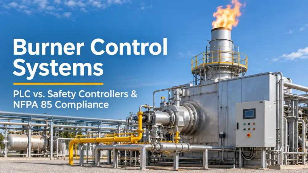
A burner control system governs ignition sequencing, flame supervision, purge timing, and emergency shutdown for every gas-fired combustion unit in an oil and gas facility. Getting the architecture right matters before equipment is ordered: NFPA 85 and ISA 84/IEC 61511 set hard requirements for which hardware qualifies, and a standard PLC does not automatically satisfy those requirements. Hero Process Solutions engineers ignition systems and integrated burner control packages for its full line of flares, combustors, and thermal oxidizers, with safety architecture designed to meet applicable standards from initial specification.
Hero Process Solutions was founded in 2011 and operates from headquarters in Kellyville, Oklahoma with operations in Midland, Texas. The company manufactures industrial flare systems in six configurations, vapor combustors, BTEX control systems, vapor recovery units, and thermal oxidizers for upstream, midstream, and refinery applications. Burner control packages are integrated into the combustion equipment product line and engineered to the site-specific fuel gas composition, flow rate, and regulatory classification of each project.
DIRECT ANSWER: BURNER CONTROL SYSTEM
A burner control system manages the start-up, shutdown, and flame safety logic for gas-fired combustion equipment. Under NFPA 85 (Boiler and Combustion Systems Hazards Code), facilities using gas-fired equipment above certain heat release thresholds must implement a Burner Management System (BMS) with proven fail-safe logic, independent of the basic process control system. Whether a standard PLC or a dedicated safety controller meets that requirement depends on the Safety Integrity Level (SIL) assigned to the safety function under ISA 84/IEC 61511, which typically ranges from SIL 1 to SIL 2 for oil and gas combustion applications.
1. How Burner Control Systems Work in Oil and Gas Operations
A burner control system performs four core functions: pre-purge, pilot ignition, main burner ignition, and flame supervision. Pre-purge removes residual unburned fuel from the combustion chamber before ignition, reducing the risk of explosive deflagration. Pilot ignition confirms a stable pilot flame before introducing main fuel flow. Flame supervision continuously monitors the flame signal from an ultraviolet or flame rod sensor, initiating a safety shutdown if the flame is lost.
Vapor combustors in oil and gas production use this same burner control system logic for vapor destruction, with the BMS managing the same start-up and flame supervision sequence applied to refinery or processing facility burners. The key difference in production applications is the variability of the waste gas fuel stream, which requires the BMS to handle a wider range of fuel compositions and flow rates than a fixed-composition industrial burner.
2. Standard PLC vs. Dedicated Safety Controller: Technical Comparison
Standard PLCs are designed for process automation tasks where a failure of the control system does not directly create a hazardous condition. A PLC failure may cause a process disruption, but the system architecture does not inherently fail to a safe state. Dedicated safety controllers, by contrast, are built to IEC 61508 standards with diagnostics, redundancy, and fault tolerance designed to ensure a fail-safe response to hardware faults.
The practical implication for burner control system selection is diagnostic coverage. A SIL 1 safety function requires a hardware fault tolerance of zero (HFT=0) with 90% or higher diagnostic coverage, achievable with certified single-channel safety PLCs from manufacturers such as Siemens, Rockwell, or Pilz. A SIL 2 function requires either HFT=1 (redundant channels) or a single-channel architecture with significantly higher diagnostic coverage, requiring a specifically certified safety controller. Thermal oxidizer applications in refinery and chemical processing environments typically carry SIL 2 requirements due to the concentration and volume of the VOC streams being destroyed.
| Parameter | Standard PLC | Dedicated Safety Controller |
|---|---|---|
| IEC 61508 Certification | Not required | Required for SIL rating |
| Fail-safe behavior | Not guaranteed | Designed to fail safe |
| Typical SIL capability | Not rated | SIL 1 to SIL 3 (model-dependent) |
| Diagnostic coverage | Low to moderate | 90%+ (SIL 1), 99%+ (SIL 2) |
| Software requirements | Standard IEC 61131-3 | Functional Safety Management required |
| Typical application | Basic process control | Burner management, ESD systems |
3. NFPA 85 Requirements for Burner Management Systems
NFPA 85 governs burner management system design for gas-fired equipment above 12.5 MMBtu/hr (single burner) or 25 MMBtu/hr (multiple burner) heat release. The standard requires a BMS that is independent of the basic process control system, with proven fail-safe logic that cannot be bypassed during normal operation.
Key NFPA 85 requirements that affect burner control system specification include the following:
- Pre-purge timing: Minimum purge volume of four air changes before ignition
- Trial for ignition: Maximum 10-second trial for ignition period for the main burner
- Flame failure response: Maximum 4-second flame failure response time before safety shutdown
- Interlock testing: Proof of closure switches required on all fuel gas shutoff valves
- Bypass management: Written procedure required for any safety function bypass during maintenance
For oil and gas production applications with smaller combustion units below the NFPA 85 heat release thresholds, API RP 556 (Instrumentation and Control Equipment for Auxiliary Fired Heaters and Steam Generators) provides analogous requirements. Many operators apply NFPA 85 logic regardless of threshold as a corporate safety standard.
KEY INSIGHT
NFPA 85 Section 4.5 requires the BMS to be “independent” of the basic process control system. This means separate hardware, separate power supply, and separate I/O, not just separate software logic running on a shared PLC. Facilities that run BMS logic on a shared controller may meet functional requirements but cannot demonstrate NFPA 85 independence.
4. Safety Integrity Level Requirements: When SIL 1 vs SIL 2 Applies
ISA 84/IEC 61511 requires a Process Hazard Analysis (PHA) and Layer of Protection Analysis (LOPA) to determine the required risk reduction for each safety function. The SIL assignment comes from LOPA, not from equipment type or facility category. A simple production site combustor and a refinery thermal oxidizer may carry the same or different SIL requirements depending on consequence severity and existing protection layers.
In practice, oil and gas burner control system applications commonly fall into two categories. SIL 1 applies to production site vapor combustors, low-pressure utility flares, and wellhead heating equipment with limited consequence scenarios. SIL 1 allows a certified single-channel safety PLC with appropriate diagnostic coverage. SIL 2 applies to high-flow refinery flares, thermal oxidizers handling high-concentration VOC streams, and equipment in occupied facility locations where a flame failure could expose personnel to hazardous concentrations. SIL 2 requires a dedicated safety controller with HFT=1 or certified high-diagnostic-coverage architecture.
The Functional Safety Management requirement under IEC 61511 means the organization must document the safety lifecycle from hazard analysis through design, commissioning, and ongoing proof testing. This documentation requirement often drives operators to select certified safety controllers even for SIL 1 applications to simplify compliance demonstration.
5. Integrating Burner Control Systems with Vapor Recovery and Flare Management
A production facility typically operates vapor recovery, flare, and combustor systems in parallel, with the burner control system needing to coordinate with all three. The common integration points are fuel gas pressure, flow rate, and composition signals that determine which combustion path handles the waste gas stream.
Vapor recovery systems on storage tanks generate a relatively consistent low-BTU gas stream, well-suited to a combustor with a stable burner control system tuned for a narrow fuel range. When the vapor recovery unit is offline or overloaded, excess gas routes to a flare, requiring the flare ignition system to confirm pilot flame before the control valve opens. The burner control system interlock logic must include a header pressure monitor and control valve sequencing that prevents simultaneous flaring and recovery, which would create a negative pressure condition in the vapor collection header and risk pulling air into the system.
6. EPA Compliance: OOOOb and Combustion System Requirements
EPA 40 CFR 60 Subpart OOOOb sets methane and VOC emission limits for new, modified, and reconstructed oil and natural gas sources. For combustion devices used for emission control, the standard requires a minimum 95% VOC emission reduction efficiency, with 98% required for flares used as air pollution control devices under 40 CFR 60.18.
The burner control system directly affects OOOOb compliance through combustion efficiency. A properly functioning BMS that maintains pilot flame and correct fuel-to-air ratio achieves the combustion efficiency required by the standard. A BMS failure that allows unburned gas to exit the flare stack or combustor represents a potential permit violation. This is one technical reason operators apply safety controller architecture to combustion equipment independent of the NFPA 85 heat release threshold: the combustion system is both a process unit and an environmental control device. Operators should review their OOOOb compliance obligations for each production site to verify that installed combustion equipment meets the current standard’s design and monitoring requirements.
CRITICAL RULE
Under 40 CFR 60.18, flares used as air pollution control devices must maintain a pilot flame at all times and achieve 98% or higher combustion efficiency. A burner control system that fails to restart the pilot after flame loss puts the facility in permit violation until the pilot is re-established. BMS response time and automatic re-ignition capability are permit compliance requirements, not just safety features.
7. Field Commissioning and Validation for Burner Control Systems
Commissioning a burner control system involves more than confirming the ignition sequence completes. NFPA 85 and IEC 61511 require proof testing of every safety function at commissioning and at defined intervals during operation: typically one to three years for SIL 1 systems and annually for SIL 2.
Hero Process Solutions’ field services team performs burner control system commissioning that includes fuel gas shutoff valve proof of closure testing, flame scanner response time verification, pre-purge timing confirmation against NFPA 85 requirements, safety function bypass testing per written procedure, and combustion efficiency verification at multiple firing rates. Documentation from commissioning forms the baseline for the ongoing proof test program required under IEC 61511. Sites that skip formal commissioning documentation often struggle to demonstrate compliance during regulatory inspections or insurance audits.
Common Mistakes in Burner Control System Specification and Integration
| Mistake | Why It Hurts Operations/Compliance | Fix |
|---|---|---|
| Using an uncertified PLC for a SIL-rated BMS | System cannot demonstrate required risk reduction; PHA/LOPA assigns SIL 1 or 2, requiring certified hardware | Perform LOPA before specifying hardware; select a certified safety controller if SIL rating applies |
| Sharing power supply between BMS and process control | Violates NFPA 85 independence requirement; a process control power failure disables the safety function | Provide dedicated, uninterruptible power to BMS hardware separate from the process control system |
| No flame failure response timing verification at commissioning | 4-second maximum NFPA 85 response time is specified but never tested; actual response may exceed limit | Test flame scanner response time at commissioning and at each proof test interval |
| Skipping pre-purge for recommissions after trips | Residual unburned fuel in combustion chamber; ignition creates deflagration risk | Configure BMS to enforce full pre-purge sequence on every start, including manual restarts after safety trips |
| No documentation of safety function bypasses | Inability to demonstrate compliance during audits; safety bypasses left in place indefinitely | Implement bypass management log with time limits and authorization requirements per NFPA 85 |
Article Summary
- A burner control system manages pre-purge, pilot ignition, main burner ignition, and flame supervision for gas-fired combustion equipment in oil and gas operations.
- NFPA 85 requires BMS hardware independent of the basic process control system for equipment above 12.5 MMBtu/hr (single burner) or 25 MMBtu/hr (multiple burner) heat release.
- ISA 84/IEC 61511 and LOPA analysis determine whether a burner management application requires SIL 1 or SIL 2 performance, not equipment type alone.
- SIL 1 applications can use a certified single-channel safety PLC with 90% or higher diagnostic coverage; SIL 2 requires a dedicated safety controller with HFT=1 or higher diagnostic coverage.
- Standard PLCs are not suitable for SIL-rated burner control applications because they are not designed or certified for fail-safe operation.
- EPA 40 CFR 60 Subpart OOOOb requires flares used as air pollution control devices to maintain pilot flame and achieve 98% or higher combustion efficiency, linking BMS performance directly to permit compliance.
- Pre-purge timing, flame failure response time, and safety function bypass management are three NFPA 85 requirements that most frequently create commissioning deficiencies.
- Field commissioning must include proof testing of all safety functions to establish the baseline for the ongoing proof test program required under IEC 61511.
- Hero Process Solutions integrates burner control systems into its combustion equipment product line, with safety architecture sized to the site classification and applicable regulatory requirements.
Frequently Asked Questions
What is the difference between a burner control system and a burner management system?
The terms are used interchangeably in most oil and gas applications. “Burner management system” (BMS) is the term used in NFPA 85 and refers specifically to the safety logic that governs startup sequencing, flame supervision, and emergency shutdown of combustion equipment. “Burner control system” is a broader term that may include the BMS plus additional process control functions such as fuel-to-air ratio control and load management. In a system that separates safety from process control functions, the BMS is the safety system and the burner control system encompasses both.
Does NFPA 85 apply to small combustors at oil and gas production sites?
NFPA 85 applies to gas-fired equipment above 12.5 MMBtu/hr (single burner) or 25 MMBtu/hr (multiple burner) heat release. Many production site combustors and low-flow flares fall below this threshold. However, ISA 84/IEC 61511 may still require a SIL-rated safety function independent of the heat release threshold if a LOPA analysis identifies the flame safety function as a required protection layer. Many operators apply NFPA 85 logic to all combustion equipment as a corporate safety standard regardless of threshold.
Can a standard Siemens or Allen-Bradley PLC be used for a burner control system?
A standard (non-safety-rated) PLC cannot be used for a SIL-rated BMS application. Siemens and Rockwell both manufacture safety-rated PLC variants (S7-300F/400F and GuardLogix, respectively) that are certified for SIL 1 and SIL 2 applications. These are functionally similar to standard PLCs but incorporate the diagnostic coverage, failure mode analysis, and functional safety management documentation required for SIL compliance. The safety-rated variant of a PLC platform is a different product from the standard variant, with different firmware, programming tools, and certification documentation.
What does NFPA 85 require for pre-purge timing on a gas-fired combustion system?
NFPA 85 requires a pre-purge volume of at least four air changes in the combustion chamber before ignition. The pre-purge time depends on the combustion air volume and the fan flow rate, so a fixed timer is not sufficient: the BMS must calculate or confirm the required purge volume based on measured air flow. For fixed-configuration equipment, the pre-purge time is calculated at commissioning and hard-set in the BMS logic based on the measured air flow rate and chamber volume. Any change to the combustion system configuration that affects chamber volume or air flow requires a recalculation of pre-purge timing.
How often must safety functions in a burner management system be proof tested?
IEC 61511 requires proof testing at intervals consistent with the SIL assignment and the probability of failure on demand (PFD) calculations in the safety requirements specification. For SIL 1 burner control systems, proof test intervals of two to three years are common. For SIL 2 systems, annual proof testing is typical. NFPA 85 requires proof testing at the intervals specified in the equipment manufacturer’s recommendations and the site’s written maintenance procedures. The proof test must verify every safety function: fuel shutoff valve response, flame scanner signal, pre-purge timing, and emergency shutdown logic.