OIL & GAS EQUIPMENT | Updated May 2026 | 9 min read
What You’ll Learn in This Guide
- How air-assist flare stacks achieve smokeless combustion through forced air injection
- The mechanical components of an air-assist flare and what each one does
- When air-assist is the right specification vs. steam-assist, gas-assist, or passive flare
- EPA 40 CFR 60 Subpart OOOOb requirements that apply to air-assist flare systems
- How to size an air-assist flare for your waste gas flow rate and composition
- Common installation and commissioning mistakes that affect smokeless performance
- API Standard 537 design requirements for air-assist flare tip and blower systems
- Hero Process Solutions air-assist product line and application range
Air-assist flare stacks are the most widely specified smokeless flare design for upstream oil and gas production, midstream gas processing, and refinery relief systems where steam is unavailable. The technology uses a motorized blower to force ambient air into the waste gas combustion zone, achieving the mixing and oxygen enrichment needed to destroy heavier hydrocarbons without visible smoke — and without the steam infrastructure that alternative designs require. Selecting the right air-assist flare stack configuration requires matching the blower capacity, tip design, and control system to your actual waste gas composition and peak flow conditions.
Hero Process Solutions, founded in 2011 and headquartered in Kellyville, OK with operations in Midland, TX, manufactures air-assist flare stacks for a full range of O&G applications — from single-well production batteries in the Permian Basin to major refinery relief systems. Every system is custom-engineered, not catalog-selected.
DIRECT ANSWER: Air-Assist Flare Stacks
An air-assist flare stack is a combustion device that uses a motorized blower to inject compressed ambient air into the waste gas stream at the flare tip, creating turbulent mixing that promotes complete combustion and eliminates visible smoke. Air-assist flare stacks are specified when waste gas composition and flow rates require smokeless performance but steam infrastructure is unavailable. Under EPA 40 CFR 60 Subpart OOOOb, all affected flares must achieve 98% combustion efficiency, which air-assist designs meet when correctly sized and operated per API Standard 537 requirements.
1. How Air-Assist Flare Stacks Work: The Combustion Mechanism
The fundamental challenge in flare combustion is achieving complete oxidation of waste hydrocarbons across a wide range of flow rates and gas compositions. Passive flares rely entirely on natural air entrainment at the flame boundary. For heavier hydrocarbons, liquids, or high-flow events, natural entrainment is insufficient and incomplete combustion produces visible black smoke — a regulatory violation.
Air-assist flare stacks solve this by mechanically supplying air directly to the combustion zone. The blower delivers a controlled volume of air into the base of the flare tip, where it mixes with the waste gas before ignition. This forced mixing achieves three things:
- Increased oxygen supply: More oxygen reaches the combustion zone, enabling more complete oxidation of carbon compounds.
- Turbulent mixing: The air injection creates turbulence that breaks up the waste gas stream and promotes intimate contact between fuel molecules and oxygen.
- Velocity control: Air injection can increase the exit velocity at the flare tip, which improves flame stability at low waste gas flow rates.
KEY INSIGHT
The smokeless operating range of an air-assist flare stack is defined as the waste gas flow rate band within which the system maintains EPA Method 22 compliance — zero visible emissions for at least 95% of any two-hour observation period. Blower sizing must target this range at maximum peak flow, not average operating flow.
2. Key Components of an Air-Assist Flare Stack
Flare tip with air injection ports: The flare tip incorporates machined ports or slots through which the blower-supplied air enters the gas stream. Tip design is specific to each application’s gas composition and flow profile, designed per API 537 requirements.
Blower system: An electric motor-driven centrifugal or positive displacement fan mounted on a dedicated skid. Blower capacity is expressed in SCFM of air delivery at the specified discharge pressure. The skid includes the motor, starter, air filter, silencer, and flow control valve.
Stack sections: Provides structural support for the tip and establishes the minimum height required for ground-level radiation compliance per API 521.
Pilot assembly: A continuous pilot flame ignites the waste gas. Air-assist flares use electronic or thermocouple ignition systems with flame monitoring per Subpart OOOOb requirements.
Liquid knockout drum: Separates any liquid carryover from the waste gas stream upstream of the flare tip, preventing flashback and unstable combustion.
Purge gas system: A continuous purge of inert gas through the flare header prevents oxygen ingress, which could create a flammable mixture within the flare stack.
3. When to Specify Air-Assist Flare Stacks
Specify air-assist when:
- Steam is unavailable at the site or would require new infrastructure to supply
- The waste gas is lean to moderately heavy (predominantly C1-C3 hydrocarbons)
- The application is a production battery, well pad, or upstream gathering system
- The site has access to electric power for blower operation
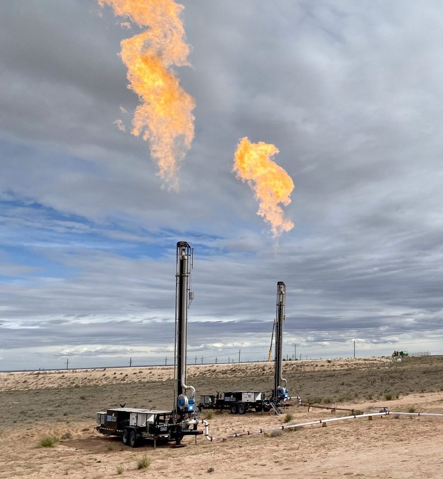
- A portable or trailer-mounted smokeless flare is needed for temporary operations
KEY INSIGHT
Air-assist flare stacks are the dominant choice for Permian Basin production operations because separator gas composition in that region — predominantly methane with moderate C2-C3 — falls comfortably within the smokeless performance range achievable with air injection, and because steam infrastructure is absent at most remote pad locations.
4. Air-Assist vs. Other Flare Types: Technical Comparison
| Flare Type | Smokeless Mechanism | Utility Needed | Best Application |
|---|---|---|---|
| Air-assist | Forced air mixing | Electric power | Upstream, midstream, lean gas |
| Steam-assist | Steam soot suppression | Steam supply | Refinery, heavy HC streams |
| Gas-assist | Fuel gas injection | Fuel gas supply | Moderate HC, gas-rich sites |
| Sonic/Coanda | High-exit-velocity tip | None (passive) | Moderate to heavy HC, high flow |
| Passive elevated | Natural entrainment | None | Lean gas, low volume |
For facilities where gas is available as a utility, gas-assist flares may offer a cost-effective alternative. For very low-flow continuous venting, vapor combustors provide an enclosed combustion solution.
5. Sizing an Air-Assist Flare Stack: Key Engineering Steps
- Characterize the waste gas: Obtain a complete gas analysis including molecular weight, composition by component, H2S content, liquid content, and Wobbe index.
- Define the flow rate envelope: Establish minimum normal flow, average operating flow, and maximum peak flow. The blower must be sized for peak flow.
- Calculate the smokeless air requirement: Based on waste gas composition and flare tip design, calculate the air volume required at peak flow to achieve smokeless combustion.
- Select the blower: Select a blower delivering the required air volume at specified discharge pressure. Include a 15-20% design margin. Specify a modulating control system.
- Determine stack height: Calculate minimum stack height from radiation and dispersion requirements per API 521.
- Specify pilot and monitoring system: Specify a continuous pilot ignition system with pilot flame monitoring per Subpart OOOOb requirements.
6. EPA 40 CFR 60 Subpart OOOOb Requirements for Air-Assist Flares
Key requirements for air-assist flare stacks under Subpart OOOOb include:
- Combustion efficiency: 98% or greater for organic compound destruction per 40 CFR 60.18.
- Pilot flame monitoring: Continuous monitoring with loss-of-pilot alarm and corrective action within specified timeframes.
- Operating parameter monitoring: Air flow rate or pressure must be monitored and maintained within design operating range. Deviations constitute a compliance event.
- Visible emissions: Zero visible emissions for at least 95% of any two-hour observation period per EPA Method 22.
CRITICAL RULE
Under Subpart OOOOb, air flow or pressure to an air-assist flare must be continuously monitored. A blower failure without immediate corrective action is a recordable deviation regardless of whether visible emissions occur. Install a blower status alarm with remote notification capability.
See the OOOOb compliance resource page for current regulatory guidance.
7. Common Air-Assist Flare Stack Specification and Installation Mistakes
| Mistake | Why It Hurts Operations/Compliance | Fix |
|---|---|---|
| Sizing blower to average flow instead of peak flow | Smokeless capacity exceeded during relief events; EPA Method 22 violation | Size blower to maximum design flow with margin |
| No modulating air control at low flow | Over-aeration at minimum flow drops combustion efficiency below 98% | Specify modulating control valve on air supply |
| Installing blower without confirmed power at flare site | Blower cannot operate; flare smokes at all flow rates | Confirm power supply early in design; specify backup power if needed |
| Omitting knockout drum | Liquid ingestion at tip causes flashback and flame instability | Include knockout drum sized for maximum liquid loading |
| Insufficient pilot monitoring | Pilot loss goes undetected; compliance event occurs | Install continuous monitoring per Subpart OOOOb requirements |
| Ignoring purge gas requirement | Oxygen ingress into flare header creates hazardous conditions | Calculate and specify continuous purge gas flow |
8. Hero Process Solutions Air-Assist Flare Systems
Hero Process Solutions’ air-assist flare product line covers applications from small production facility sizes to large refinery relief systems. Each system is engineered from a waste gas analysis. For temporary applications, the Hero Process Solutions rental fleet includes trailer-mounted air-assist units available for rapid deployment. Field commissioning and startup support is available through Hero PS Field Services.
Contact Hero Process Solutions at sales@hero-ps.com or (918) 941-2166 for application engineering support.
Article Summary
- Air-assist flare stacks use a motorized blower to inject ambient air into the waste gas combustion zone, achieving smokeless performance through forced mixing and oxygen enrichment.
- Key components include the flare tip with air injection ports, blower skid, stack, continuous pilot assembly, liquid knockout drum, and purge gas system.
- Air-assist is the standard specification for upstream production locations without steam infrastructure where waste gas is lean to moderately heavy.
- Blower sizing must be based on maximum peak waste gas flow, not average flow.
- Modulating air control is required to avoid over-aeration at low flow conditions, which reduces combustion efficiency below the 98% EPA threshold.
- EPA 40 CFR 60 Subpart OOOOb requires continuous pilot flame monitoring, assist medium monitoring, and zero visible emissions for 95% of any two-hour observation period.
- Air-assist blower failure must be alarmed and corrected promptly; loss of assist air is a recordable compliance deviation under Subpart OOOOb.
- API Standard 537 governs engineering requirements for air-assist flare tip design.
- Common spec mistakes include omitting the knockout drum, failing to specify purge gas, and selecting air-assist for heavy C4+ waste gas streams.
- Hero Process Solutions engineers custom air-assist flare stacks and offers rental units for temporary production applications.
Frequently Asked Questions
What is an air-assist flare stack and how does it differ from a regular flare?
An air-assist flare stack uses a motorized blower to force ambient air into the waste gas stream at the flare tip. A standard elevated flare relies on natural air entrainment, which is insufficient for heavier hydrocarbons or high-flow conditions and can produce visible smoke. The forced air injection provides more consistent oxygen delivery and turbulent mixing, achieving smokeless combustion across a wider operating range without requiring steam infrastructure.
How do I know if my site needs an air-assist flare stack?
If your waste gas includes hydrocarbons heavier than methane (C2 and above), or if your facility is subject to EPA Method 22 visible emission requirements, a passive flare may not provide reliable smokeless performance. Sites handling separator gas from oil production, gas processing plant vents, or any stream with moderate to heavy hydrocarbon content should evaluate air-assist flare stacks, particularly where steam is unavailable.
Can an air-assist flare stack handle high-flow relief events?
Yes, provided the blower is sized to the maximum relief flow rate. The blower must deliver sufficient air to maintain the smokeless air-to-fuel ratio at peak flow. A modulating control system allows the air supply to ramp up rapidly when flow increases, maintaining smokeless performance during the transition from low normal flow to high relief flow.
What maintenance does an air-assist flare stack require?
Routine maintenance includes blower motor and bearing inspection, impeller cleaning, air filter replacement, control valve calibration, pilot assembly inspection, knockout drum liquid level checks, and purge gas flow rate verification. The Subpart OOOOb monitoring system also requires periodic calibration and function testing. Hero Process Solutions’ aftermarket support program provides maintenance contracts for air-assist flare systems.
Does an air-assist flare stack require a liquid knockout drum?
Yes. A liquid knockout drum upstream of the flare tip is required for any flare system that may receive liquid carryover in the waste gas stream. Liquid ingestion at the flare tip can cause flashback, irregular combustion, and physical damage to the tip internals. The knockout drum must be sized for the maximum expected liquid loading.