

OIL & GAS EQUIPMENT | Updated May 2026 | 8 min read
What You’ll Learn in This Guide
- The mechanical difference between fixed exit slot and variable exit area sonic flare tip designs
- How fixed exit slot tips achieve choked flow and what their turndown limits are
- How variable exit area tips extend turndown by mechanically adjusting throat area
- The control mechanisms used in variable exit area designs
- When fixed exit slot tips are the right answer despite limited turndown
- When variable exit area tips are worth the additional mechanical complexity
- Common selection mistakes between the two tip design philosophies
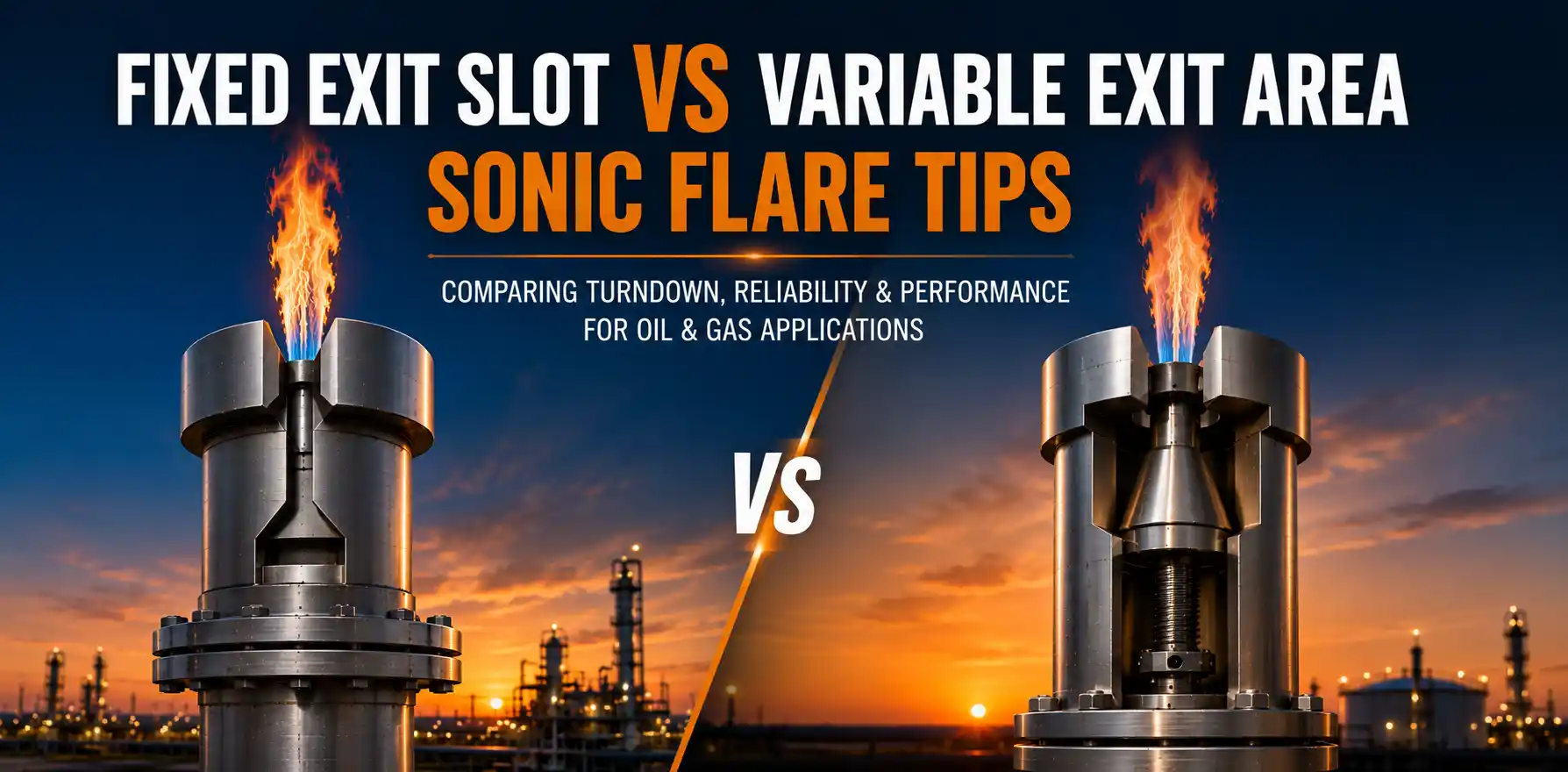
Sonic flare tips fall into two main design philosophies. Fixed exit slot tips have a fixed throat geometry and rely on multi-point staging or operational constraints to handle turndown. Variable exit area tips mechanically adjust the throat area to maintain choked-flow conditions across a wider operating range from a single tip. The choice between them is one of the more nuanced engineering decisions in sonic flare specification — and one where understanding the trade-offs matters more than picking the “better” technology. This guide walks through the design difference, the operating implications, and when each approach wins.
Hero Process Solutions, founded in 2011 and headquartered in Kellyville, Oklahoma with operations in Midland, Texas, manufactures sonic flares with Coanda-profile tip designs across the configuration range needed for upstream, midstream, refining, and petrochemical service. This guide draws on the engineering trade-offs we evaluate on every sonic flare project.
DIRECT ANSWER: Fixed exit slot sonic flare tips have a fixed throat geometry sized for the design flow with practical single-tip turndown of 3:1 to 5:1. Variable exit area sonic flare tips mechanically adjust the throat area (using a movable cone, slot, or annulus) to maintain choked-flow conditions across a wider range, typically delivering 10:1 to 20:1 single-tip turndown. Choose fixed exit slot for steady continuous service with limited flow variation and lower CAPEX. Choose variable exit area when wider single-tip turndown is required and the additional mechanical complexity is acceptable. For very wide turndown requirements (above 50:1), multi-point staged configurations with multiple fixed exit slot tips typically outperform single variable exit area tips.
1. Fixed Exit Slot Sonic Flare Tip Design
A fixed exit slot sonic flare tip has a fixed throat geometry — typically a circular nozzle, annular slot, or Coanda-profiled exit — sized for the design peak flow rate. The throat dimensions are calculated from the choked-flow mass equation using gas k value, upstream absolute pressure, and upstream absolute temperature.
At design flow, the gas exits the throat at sonic velocity. The Coanda profile (or comparable shaping) downstream of the throat optimizes the turbulent mixing zone for smokeless combustion. Combustion happens in the atmosphere around the tip exit with ambient air entrainment driven by the high-velocity, high-turbulence jet.
Single-tip fixed exit slot designs typically deliver 3:1 to 5:1 turndown while maintaining choked-flow conditions. Below the choking threshold, exit velocity drops below sonic, the turbulent mixing zone weakens, and smokeless behavior is lost. For wider turndown service, fixed exit slot designs are deployed in multi-point staged configurations with multiple tips of different sizes.
2. Variable Exit Area Sonic Flare Tip Design
A variable exit area sonic flare tip mechanically adjusts the throat area in response to changing waste-gas flow. Three mechanical approaches are common.
Movable cone or plug. A cone or plug positioned within the throat moves axially to expand or contract the effective throat annulus. At low flow, the cone moves into the throat to reduce throat area and maintain choked conditions. At high flow, the cone retracts to expand the throat. Position is controlled by actuator linked to upstream pressure or flow measurement.
Adjustable slot width. Annular slot tips with mechanically adjustable slot width can change throat area while maintaining the slot geometry that produces the Coanda effect. The mechanism is typically a sliding ring or cone-shaped throttle.
Multiple parallel slots or nozzles with individual valves. Each nozzle has its own valve and the control system opens or closes nozzles in sequence as flow changes. This approach blurs into multi-point staging at the tip level rather than the manifold level.
Variable exit area tips typically deliver 10:1 to 20:1 single-tip turndown — a meaningful extension of the fixed exit slot range — at the cost of additional mechanical complexity in the tip itself.
KEY INSIGHT: The single-tip turndown advantage of variable exit area designs is most valuable when site constraints (footprint, height limits, control system simplicity) make multi-tip staging impractical. Where staging is feasible, multi-tip fixed exit slot configurations often outperform single variable exit area tips on both turndown range and reliability.
3. Control Mechanisms for Variable Exit Area Tips
Variable exit area tip control loops use two main inputs and produce one main output. The inputs are upstream pressure at the manifold and waste-gas mass flow rate at the inlet. The output is actuator position controlling the throat area.
The control logic maintains a target choked-flow pressure ratio across the throat. As waste-gas flow rises, upstream pressure would tend to rise above the target if throat area is held constant. The control loop expands the throat area to maintain choked conditions at the new flow rate. As flow drops, the loop contracts the throat area to maintain choking at the lower flow.
Actuator response time, hysteresis, and minimum step size are critical tuning parameters. Too fast a response causes throttle hunting at flow rates near steady state; too slow a response allows pressure excursions during transient flow events. Typical response time is on the order of 2 to 10 seconds for tip area changes.
4. When Fixed Exit Slot Tips Win
Fixed exit slot tips win on five application categories.
Steady continuous service with limited flow variation. A midstream gas plant with stable inlet flow within a 3:1 to 5:1 turndown range works well with single-tip fixed exit slot design.
Multi-tip staged configurations where each individual tip operates within its choked-flow window. The combination of multiple fixed-area tips and sequencing valves delivers very wide overall system turndown without per-tip complexity.
Lower CAPEX projects. Fixed exit slot tips have no moving parts, simpler manufacturing, lower per-tip cost, and shorter lead times than variable exit area designs.
High-reliability requirements. No moving parts means no mechanical wear, no actuator failures, and predictable long-term performance. For emergency relief duty where the flare may fire once a year, fixed exit slot simplicity is operationally valuable.
Service environments where mechanical adjusters are vulnerable. Sour service, high-particulate streams, and harsh weather environments can be hard on variable exit area mechanisms. Fixed exit slot tips tolerate these environments better.
5. When Variable Exit Area Tips Win
Variable exit area tips win when the application combines wide single-tip turndown with site constraints that make multi-tip staging impractical.
Single-tip wide-turndown service. When the application requires 10:1 to 20:1 turndown from a single tip — and site footprint, height limits, or control complexity rule out multi-tip staging — variable exit area is the only path.
Continuous high-pressure variable-flow service. Petrochemical and refinery applications with continuous flow and significant flow variability sometimes favor variable exit area tips over multi-tip staging.
Retrofit applications where existing stack and manifold cannot accommodate multi-tip configuration. The retrofit constraint forces the wider turndown into the tip itself, which favors variable exit area.
6. Tip Design Comparison Matrix
| Characteristic | Fixed Exit Slot | Variable Exit Area |
|---|---|---|
| Single-tip turndown | 3:1 to 5:1 | 10:1 to 20:1 |
| Mechanical complexity | Low (no moving parts) | High (actuator, throat adjuster) |
| CAPEX per tip | Lower | Higher (typically 50% to 100% premium) |
| Maintenance burden | Lower (inspection only) | Higher (actuator service) |
| Reliability over service life | Higher (no wear parts) | Moderate (actuator wear) |
| Response time to flow changes | Instant (passive) | 2 to 10 seconds (actuator) |
| Best in multi-tip configurations | Yes (preferred for staging) | No (defeats purpose) |
| Sour service tolerance | Better | Limited |
The right choice depends on application profile, not absolute superiority of either design. Hero’s industrial flare systems portfolio includes both fixed exit slot and variable exit area tip designs sized for the full range of sonic flare applications.
7. OOOOb 98% DRE Considerations
EPA 40 CFR 60 Subpart OOOOb requires 98% Destruction and Removal Efficiency across the full operating range on affected sonic flares. Both fixed exit slot and variable exit area designs can satisfy OOOOb when properly configured.
For single-tip fixed exit slot service, OOOOb compliance is achieved across the choked-flow window. Operations outside the choked-flow window must be managed through operational procedures or supplementary backup combustion. For wider OOOOb-compliant turndown, multi-point staged configurations of fixed exit slot tips are the standard answer.
For variable exit area tips, OOOOb compliance depends on the control loop reliably maintaining choked conditions across the operating range. The actuator and control logic must be qualified for OOOOb-grade reliability and monitored continuously. Visit our EPA OOOOb compliance resource for the full requirements.
8. Common Tip Design Selection Mistakes
| Mistake | Why It Hurts | Fix |
|---|---|---|
| Specifying variable exit area to avoid multi-tip staging complexity | Single-tip turndown still falls short of staged configuration capability | Compare staged fixed exit vs single variable exit on turndown and CAPEX |
| Specifying fixed exit slot for service with wide composition variability | Composition shifts the choking threshold, single tip cannot adapt | Specify variable exit area or staged fixed exit for composition-variable service |
| Skipping actuator OOOOb qualification on variable exit area designs | Actuator failure compromises 98% DRE compliance | Specify OOOOb-qualified actuator with continuous status monitoring |
| Specifying variable exit area for sour service | Mechanical adjuster degrades in H₂S environment | Specify fixed exit slot for sour service with appropriate metallurgy |
| Comparing only CAPEX without lifecycle reliability | Variable exit area maintenance and actuator service offsets simpler integration | Run full lifecycle analysis including maintenance burden |
| Treating variable exit area as a drop-in for fixed exit slot | Control logic and monitoring differ; design must be reconsidered | Redesign control system to match variable exit area requirements |
Article Summary
- Fixed exit slot sonic flare tips have fixed throat geometry with practical single-tip turndown of 3:1 to 5:1.
- Variable exit area sonic flare tips mechanically adjust throat area to deliver 10:1 to 20:1 single-tip turndown.
- Three variable exit area mechanisms are common: movable cone or plug, adjustable slot width, and multiple parallel valved nozzles.
- Fixed exit slot tips win on steady continuous service, multi-tip staged configurations, lower CAPEX, high reliability, and harsh-environment service.
- Variable exit area tips win when single-tip wide turndown is required and multi-tip staging is impractical.
- Multi-tip staged configurations of fixed exit slot tips often outperform single variable exit area tips on overall turndown and reliability.
- Both designs satisfy OOOOb 98% DRE when properly configured; variable exit area requires actuator OOOOb qualification.
- Hero Process Solutions manufactures both fixed exit slot and variable exit area sonic flare tip designs from Kellyville, Oklahoma.
Frequently Asked Questions
What is the difference between fixed exit slot and variable exit area sonic flare tips?
A fixed exit slot tip has a fixed throat geometry sized for the design flow with single-tip turndown of 3:1 to 5:1 within the choked-flow window. A variable exit area tip mechanically adjusts the throat area (using a movable cone, adjustable slot, or sequenced parallel nozzles) to maintain choked conditions across a wider range, typically delivering 10:1 to 20:1 single-tip turndown at the cost of additional mechanical complexity.
When should I choose a fixed exit slot tip over a variable exit area tip?
Choose fixed exit slot when the application is steady continuous service with limited flow variation (3:1 to 5:1 turndown is adequate), when multi-tip staged configurations are feasible, when lower CAPEX or simpler maintenance is the priority, or when the service environment (sour, particulate-laden) makes mechanical adjusters vulnerable. For applications requiring wider single-tip turndown without site constraints supporting multi-tip staging, variable exit area becomes the better choice.
How do variable exit area tips maintain choked flow across wider turndown?
The mechanism adjusts the throat area in response to changing waste-gas flow. As flow rises, the throat area expands to accommodate higher mass flow while maintaining the choked-flow critical pressure ratio. As flow drops, the throat area contracts to maintain choking at the lower flow. A control loop reads upstream pressure and flow rate, drives an actuator to position the throat adjuster, and verifies choked-flow conditions across the operating envelope.
Are variable exit area tips suitable for sour service?
Limited. The mechanical actuator and throat adjuster mechanisms are vulnerable to corrosion and degradation in H₂S-laden environments. For sour service, fixed exit slot tips with appropriate corrosion-resistant metallurgy are typically the better choice. Sour service applications requiring wider turndown often use staged configurations of fixed exit slot tips rather than variable exit area designs.
Can variable exit area tips meet OOOOb 98% DRE?
Yes, when the control loop reliably maintains choked-flow conditions across the operating range and the actuator is OOOOb-qualified with continuous status monitoring. The compliance documentation must demonstrate that the actuator and control logic perform reliably under realistic operating conditions. Variable exit area tip OOOOb compliance is more complex than fixed exit slot compliance because the additional mechanical control loop must be qualified and monitored.
Can Hero Process Solutions supply both tip design philosophies?
Yes. Hero manufactures sonic flares with Coanda-profile tips in both fixed exit slot and variable exit area designs, sized for upstream, midstream, refining, and petrochemical applications. The selection between the two philosophies is supported by Hero’s engineering team during project assessment with consideration of turndown requirements, service environment, site constraints, and OOOOb compliance pathway.