OIL & GAS EQUIPMENT | Updated May 2025 | 10 min read
- The engineering principles that govern flare system design in oil and gas applications
- All major flare system types and which process conditions each is designed for
- The individual components that make up a complete flare system and what each does
- EPA 40 CFR 60 Subpart OOOOb requirements that apply to flare system design and operation
- API Standard 537 and its role in flare tip and system design
- How to sequence a flare system design from gas characterization through tip selection
- Common design errors that create compliance problems and how to avoid them
Flare system design for oil and gas is an engineering discipline with regulatory, safety, and process performance consequences that start at the gas characterization phase and extend through the choice of flare tip geometry, pilot design, and monitoring system. A flare system sized and designed without reference to the actual waste gas composition, heating value variability, and applicable EPA 40 CFR 60 Subpart OOOOb requirements will produce a unit that either underperforms on combustion efficiency, fails opacity standards, or requires expensive modification after installation.
Hero Process Solutions, founded in 2011 and headquartered in Kellyville, OK with operations in Midland, TX, designs and fabricates flare systems for upstream oil and gas production, midstream gathering, refinery, and petrochemical applications. The engineering team works from gas characterization through system commissioning, with manufacturing at the Kellyville facility and field service support from both locations.
Flare system design for oil and gas requires: waste gas characterization (flow rate, heating value, composition), flare type selection (air-assist, steam-assist, gas-assist, or utility), radiation heat flux analysis per API RP 521, liquid knockout drum design upstream of the tip, and pilot system design per 40 CFR 60.18 for EPA OOOOb compliance. API Standard 537 governs flare tip design details for the petroleum and gas industries. All flare systems must achieve 98% combustion efficiency when serving OOOOb-affected sources.
1. Gas Characterization: The Starting Point for Every Flare Design
No flare system can be correctly designed without first characterizing the waste gas stream it will handle. Gas characterization defines the operating envelope the system must cover.
Flow Rate and Flow Variability
The design flow rate is the maximum sustained flow the flare must handle without exceeding its capacity or going out of compliance. For production site flares, this includes the maximum relief scenario, not just normal operations. Flare tips are typically sized for the maximum relief case (a conservative scenario), with the understanding that the tip must also maintain stable combustion at the minimum normal flow rate.
The turndown ratio — the ratio of maximum to minimum stable operating flow — must be evaluated for every flare design. A flare tip that achieves 98% efficiency at full flow but extinguishes at 5% flow is not a compliant design for applications where low-flow operation is expected.
Heating Value
The net heating value of the waste gas in BTU/scf determines whether the flare can sustain stable combustion at the tip. The EPA’s 40 CFR 60.18(b)(2) minimum heating value threshold is 300 BTU/scf for most flares. Gas streams below this threshold (common in certain gas processing applications) require enrichment with higher-heating-value gas or an alternative combustion approach.
Rich associated gas from oil production (typically 1,000 to 1,400 BTU/scf) presents the opposite challenge: it burns hot and can overheat tip components at high flow rates if the tip geometry is not designed for the heating value.
Gas Composition and Special Constituents
Beyond heating value, the gas composition drives material selection and emission characterization:
- H2S content determines sour service materials and sulfur dioxide emission calculations
- Heavy hydrocarbon content (C5+) determines the smokeless combustion requirements
- Nitrogen or CO2 diluents reduce heating value and may require tip design adjustment
- Oxygen content creates a safety-critical explosion risk condition that requires careful handling
2. Flare System Types and When to Use Each
The choice of flare system type is driven by the waste gas composition, flow rate, smokeless requirements, and available utilities.
Air-Assist Flare Systems
Air-assist flares inject forced combustion air into the base of the flare tip using a motor-driven blower. This additional air enables smokeless combustion of heavier hydrocarbons that would otherwise produce visible black smoke. Air-assist is the standard design for high-capacity flares handling rich associated gas from oil production in the Permian Basin and similar plays. Hero Process Solutions’ air-assist flare systems are designed for a broad flow rate range with turndown capability that maintains smokeless combustion at partial loads.
Steam-Assist Flare Systems
Steam-assist flares inject steam into the flare tip to achieve smokeless combustion through a combination of steam momentum and oxygen addition. Steam-assist is the traditional choice at refineries and chemical plants where steam is a readily available utility. In upstream O&G applications, steam is rarely available, so steam-assist is uncommon in production environments.
Gas-Assist Flare Systems
Gas-assist flares use a portion of the waste gas itself (or fuel gas) to create turbulence and air entrainment at the flare tip through high-velocity jets. This design achieves smokeless combustion without requiring a blower motor or steam supply. Gas-assist is well-suited for sites where power availability is limited and the gas stream has sufficient pressure and heating value.
Utility and Low-Flow Flares
Utility flares are simple orifice-type or multi-point burner flares without forced air, steam, or gas assist. They are suitable for lean gas streams, emergency relief applications where visible smoke is tolerable during short-duration events, and locations where smokeless operation is not required. Low-flow flares are commonly deployed at remote production sites for continuous low-volume venting applications.
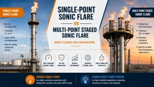
Sonic (Coanda) Flares
Sonic or Coanda flares operate at sonic velocity at the tip exit, using the Coanda effect to entrain ambient air and achieve smokeless combustion without external utilities. These designs are highly efficient for high-flow, high-pressure applications at gathering stations and gas processing plants. The high-pressure requirement (typically above 15 PSIG at the tip) limits their applicability to pressurized relief streams.
| Flare Type | Smokeless | External Utility | Best Application | Hero PS Product |
|---|---|---|---|---|
| Air-assist | Yes, at design flow | Blower motor | Rich gas, high-capacity upstream | Air-Assist Flares |
| Steam-assist | Yes | Steam | Refineries, chemical plants | N/A — upstream focus |
| Gas-assist | Yes | Fuel gas/pressure | Remote sites, limited power | Gas-Assist Flares |
| Utility/low-flow | Smoke at high flow | None | Lean gas, emergency, low-flow | Low-Flow Flares |
| Sonic/Coanda | Yes | High pressure | High-pressure relief, gas plants | Sonic Flares |
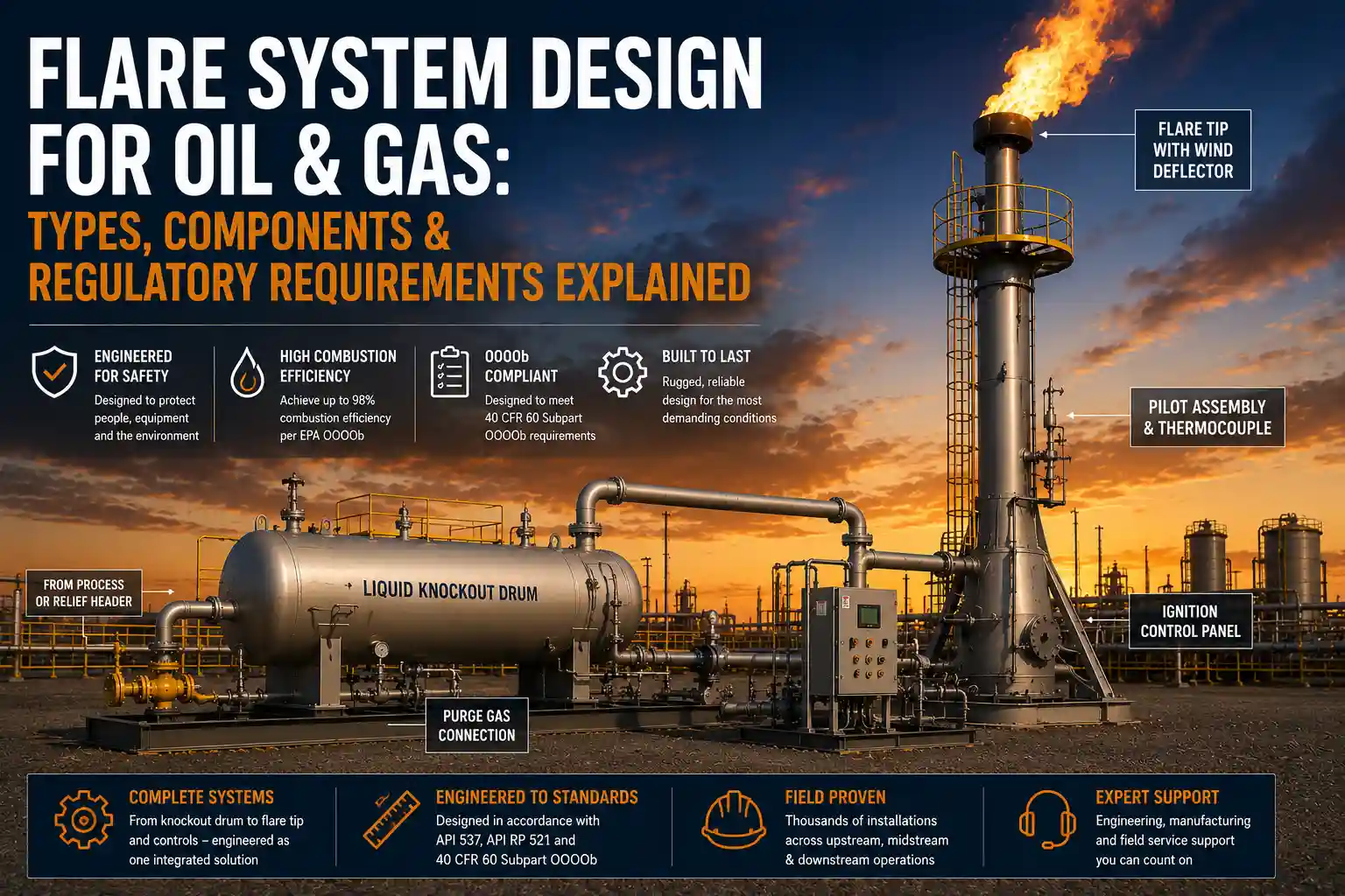
3. Key Flare System Components
A complete flare system consists of multiple integrated components. Each component must be correctly designed and matched to the others for the system to perform.
Flare Stack
The stack elevates the combustion point above the surrounding equipment and personnel. Stack height is determined by the thermal radiation heat flux analysis per API RP 521. The allowable ground-level radiation intensity (typically 1,500 BTU/hr·ft² for continuous exposure of unprotected personnel) combined with the maximum design heat release rate sets the minimum required stack height at a given location. Stack structural design must account for wind loading per applicable building codes, along with the dynamic loads from flame and gas flow.
Flare Tip
The flare tip is the combustion device at the top of the stack. API Standard 537 (Flare Details for General Refinery and Petrochemical Service) provides design guidance for flare tips, including tip geometry, nozzle configurations, and pilot placement. Flare tip selection is the single most critical engineering decision in a flare system — the tip geometry determines combustion efficiency, turndown range, smokeless performance, and noise level.
Pilot Assembly
The pilot flame provides the continuous ignition source required by 40 CFR 60.18. A well-designed pilot system includes: pilot burner with stable flame geometry, electronic ignition (spark igniter), thermocouple or UV scanner for flame detection, and auto-reignition capability (mandatory for unattended applications).
Liquid Knockout Drum
Every flare system requires a liquid knockout drum upstream of the flare tip. For fixed flare systems, the KO drum is typically a horizontal vessel in the flare header, sized per API RP 521.
Purge Gas System
A purge gas connection prevents air from entering the flare header during low-flow or no-flow periods. Air ingress into a flare header creates an explosive mixture inside the system. The purge gas (typically fuel gas, nitrogen, or sales gas at very low flow rates) keeps the header oxygen-free at all times.
Ignition Control Panel
The ignition control panel contains the pilot gas regulators, high/low pressure shutoffs, ignition controls, and flame monitoring outputs. For larger flare systems, the control panel also includes the blower motor controls (for air-assist systems) and connections to the facility DCS or remote monitoring system.
API Standard 537 was last updated in 2017 and is the primary reference standard for flare tip design in the petroleum and natural gas industries. Unlike API RP 521 (which covers the overall flare system), API 537 focuses on the flare tip component specifically: nozzle design, staging configurations, noise performance, and smokeless capacity. A flare vendor who does not design to API 537 may not understand the performance envelope of their own tip geometry.
4. EPA Regulatory Requirements for Flare System Design
40 CFR 60.18: Standards of Performance for Visible Emissions
40 CFR 60.18 establishes performance standards for all flares subject to EPA New Source Performance Standards, including those at oil and gas production facilities regulated under Subpart OOOOb. The key requirements from 40 CFR 60.18:
- Continuous pilot flame (at least one)
- No visible emissions (opacity below 5%) except during startup (one 5-minute period per startup event) and periods of malfunction
- Net heating value of the combustible gas at the tip: at least 300 BTU/scf, or at least 200 BTU/scf for steam-assisted flares
- Hydrogen content limit: if the gas stream has a high hydrogen content, the flare must be designed to handle hydrogen combustion safely
40 CFR 60 Subpart OOOOb: Methane and VOC from Oil and Gas
For flares at oil and natural gas production, processing, and transmission facilities that are affected facilities under OOOOb compliance (construction, modification, or reconstruction after December 6, 2022), the standard requires:
- 98% combustion efficiency from the flare system
- Compliance with 40 CFR 60.18 pilot and visible emission requirements
- Recordkeeping demonstrating gas composition, flow rates, and monitoring results
- Deviation reporting for any period when the pilot flame is out or efficiency targets are not met
API RP 521: Pressure-Relieving and Depressuring Systems
While not an EPA standard, API RP 521 is the industry engineering standard for the design of the relief header, knockout drum, and overall flare system layout. It provides the radiation heat flux methodology used to establish stack height and exclusion zone distances. Most operating companies’ internal standards reference API RP 521 as the design basis.
The 98% combustion efficiency requirement under EPA 40 CFR 60 Subpart OOOOb is a design requirement, not just an operational target. The flare system must be designed and documented to achieve 98% at the expected range of flow rates and gas compositions. A system that achieves 98% at design flow but not at turndown or with gas composition variability is not a compliant design under OOOOb.
5. Flare System Design Sequence
A well-executed flare system design follows this sequence:
- Gas characterization: Define flow rate range, heating value, composition, H2S content, liquid loading
- Regulatory classification: Determine if the source is OOOOb-affected; identify applicable federal and state permits
- Flare type selection: Based on gas composition, smokeless requirements, available utilities, and site constraints
- Radiation analysis: Per API RP 521, calculate required stack height for the design heat release rate
- Knockout drum design: Size per API RP 521 for the maximum design gas flow rate
- Tip selection and sizing: Per API Standard 537, based on flow rate, heating value, and required turndown
- Pilot system design: Specify auto-reignition, thermocouple monitoring, and control panel per 40 CFR 60.18
- Structural design: Stack wind load calculations, foundation design, guy wire layout if required
- Documentation: Compile design calculation package for regulatory submittal and future inspection reference
6. Coordination with Vapor Control and Process Equipment
A flare system does not operate in isolation. It is the terminal point of a gas handling system that includes separators, knockout drums, VRUs, and vapor combustors. The flare must be designed to accept gas from all of these upstream sources under both normal operating conditions and upset scenarios.
VRU Bypass to Flare
When a VRU compressor trips or goes offline for maintenance, the tank vent gas must have an alternative route to prevent overpressure at the separator or storage tank. The VRU bypass to the flare is the standard solution. The flare system must be sized to handle this bypass gas volume in addition to its normal relief load.
Integration with Hero Process Solutions Product Line
Hero PS designs flare systems as part of an integrated product line that includes 3-phase separators, liquid knockout systems, BTEX condenser systems, and vapor combustors. This allows the engineering team to size each component against the others in the complete gas handling train, rather than optimizing each piece independently and discovering integration problems during commissioning.
Common Design Mistakes to Avoid
| Mistake | Why It Hurts Operations/Compliance | Fix |
|---|---|---|
| Designing for average gas composition, not worst case | System fails compliance during high-liquid or low-heating-value gas events | Design for the full expected range of gas composition and heating value |
| Stack height set without radiation analysis | Personnel or equipment exposure to excessive thermal radiation | Complete API RP 521 radiation heat flux analysis before fixing stack height |
| No purge gas system | Air ingress into flare header; explosion risk | Specify purge gas connection as mandatory in every flare system design |
| Single pilot with no auto-reignition | Pilot outage during unattended operation = OOOOb violation | Specify auto-reignition and thermocouple monitoring for all unattended flare applications |
| Tip selected without turndown analysis | System fails combustion efficiency at low flow; compliance gap | Verify stable combustion efficiency at minimum expected flow rate before selecting tip |
| Omitting KO drum from flare header | Liquid damage to flare tip; visible emissions; potential fire hazard at tip | Include KO drum in all flare system designs as a non-negotiable component |
Article Summary
- Flare system design for oil and gas begins with waste gas characterization: flow rate range, heating value, composition, and H2S content.
- Flare type selection (air-assist, gas-assist, steam-assist, utility, or sonic) is driven by gas composition, smokeless requirements, and available utilities.
- Stack height is determined by API RP 521 thermal radiation heat flux analysis at the maximum design flow rate.
- Key components include the flare tip (per API Standard 537), pilot assembly with auto-reignition, liquid knockout drum, purge gas system, and ignition control panel.
- EPA 40 CFR 60.18 requires a continuously burning pilot, no visible emissions (opacity below 5%), and minimum heating value of 300 BTU/scf.
- EPA 40 CFR 60 Subpart OOOOb requires 98% combustion efficiency from flares at affected oil and gas production facilities.
- The 98% efficiency requirement is a design obligation, not just an operational target — the system must achieve it across the full expected operating range.
- Flare systems must be designed in coordination with upstream separators, VRUs, and knockout drums to handle both normal and upset gas volumes.
- Hero Process Solutions designs complete flare systems from gas characterization through commissioning, integrating flares with the full site vapor control equipment train.
Frequently Asked Questions
What are the EPA requirements for flare system design in oil and gas?
Flares at oil and gas facilities subject to EPA 40 CFR 60 Subpart OOOOb must meet: 98% combustion efficiency, a continuously burning pilot flame verified by thermocouple or equivalent, no visible emissions (opacity below 5%) except during startup events, and a minimum net heating value of 300 BTU/scf at the flare tip per 40 CFR 60.18. These requirements apply to flares serving OOOOb-affected sources constructed, modified, or reconstructed after December 6, 2022.
What is API Standard 537 and how does it affect flare design?
API Standard 537 (Flare Details for General Refinery and Petrochemical Service) is the American Petroleum Institute’s technical standard for flare tip design. It covers tip geometry, nozzle configurations, multi-point staging, noise performance, and other flare tip engineering details. Designing a flare tip to API 537 provides a documented technical basis for the tip’s performance claims and ensures the design follows industry-accepted engineering practice.
How do you determine the right stack height for a flare system?
Stack height is determined by thermal radiation heat flux analysis per API RP 521. The analysis calculates the heat release rate at the maximum design gas flow, then determines the minimum stack height that places the maximum ground-level radiation intensity within the allowable limits: 1,500 BTU/hr·ft² for continuous exposure of unprotected personnel, and higher limits for areas accessible only by protected personnel or where public access is excluded.
What is the difference between a utility flare and an air-assist flare?
A utility flare is a simple combustion device without forced air, steam, or gas assist. It relies on natural draft for combustion air and is suitable for lean gas streams where smokeless operation is not required or for emergency relief scenarios. An air-assist flare uses a motor-driven blower to inject combustion air into the flare tip, enabling smokeless combustion of heavier hydrocarbon streams. Air-assist is required when the waste gas contains significant C4+ hydrocarbons that would produce visible black smoke in a utility-type flare.
How long does it take to design and fabricate a flare system?
Engineering and fabrication timelines for a flare system vary by complexity. A standard upstream utility or air-assist flare system for a production site typically has a combined engineering and fabrication lead time of 8 to 16 weeks. Larger systems, sour gas service, or systems with extensive custom engineering (multi-tip staging, SCADA integration, complex structural design) may require 20 to 30 weeks. Hero Process Solutions can provide a project-specific timeline with the initial engineering proposal.