

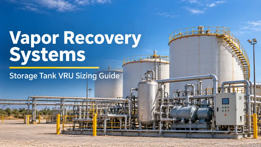
Upstream oil and gas production sites generate hydrocarbon vapors continuously from crude oil and condensate storage tanks. A properly sized vapor recovery system for storage tanks is an important emission-control solution for upstream production facilities.
Undersized and oversized vapor recovery units (VRUs) can create compressor surging, unacceptable suction pressure swings, downstream liquid carryover, equipment wear, and compliance exposure.
Hero Process Solutions, founded in 2011 and headquartered in Kellyville, Oklahoma, with operations in Midland, Texas, engineers vapor recovery systems for upstream production across the Permian Basin, Mid-Continent, Appalachian, and Rocky Mountain basins.
What You’ll Learn in This Guide
- How flash gas generation determines VRU sizing at tank batteries
- How to estimate average and peak vapor generation
- Why compressor capacity is commonly based on average vapor throughput
- How suction scrubbers prevent liquid carryover
- Differences between single-tank and multi-tank VRU configurations
- How EPA 40 CFR 60 Subpart OOOOb affects storage tank emission control
- When to use a vapor combustor instead of a VRU
- Common VRU sizing mistakes that cause performance and compliance problems
How Flash Gas Generation Determines VRU Sizing at Tank Batteries
Flash gas is the primary vapor source at upstream crude oil and condensate storage facilities. When production fluids drop from separator pressure to atmospheric storage pressure, dissolved light hydrocarbons, including methane, ethane, propane, butane, and natural gas liquids, come out of solution.
The volume of flash gas generated per barrel depends on crude oil composition, upstream separator operating pressure, crude API gravity, and temperature.
Typical flash gas rates at upstream tank batteries range from 100 to 800 standard cubic feet per barrel (SCF/bbl) of oil processed. Light, gassy crudes can flash at the high end of that range, while heavy crude with lower dissolved gas content may generate flash gas at approximately 100 to 200 SCF/bbl.
For example, a tank battery processing 500 BPD at 800 SCF/bbl produces four times the vapor load of a similar facility processing 500 BPD at 200 SCF/bbl, even though the oil throughput is identical.
How to Estimate Vapor Load
- Identify the upstream separator operating pressure in psig.
- Obtain or estimate crude oil API gravity and gas-oil ratio (GOR) from separator test data or nearby well analogs.
- Calculate the average vapor generation rate in MCFD or MMSCFD using flash calculations or EOS modeling.
- Apply a peak-to-average ratio to account for production swings, truck unloading, tank filling cycles, and thermal breathing.
At active upstream sites, the peak-to-average ratio can vary based on the number of tanks, tank turnover frequency, and whether produced-water tanks with dissolved gas are connected to the vapor header.
Compressor Capacity for a Storage Tank VRU
A commonly applied field rule for VRU compressor sizing is to install a unit rated for approximately twice the average vapor generation rate. At this capacity, the compressor can operate at approximately 50% duty cycle under average load conditions while maintaining capacity for peak vapor events.
What the 2x Average Capacity Provides
- Surge capacity for tank filling events and peak thermal breathing
- Adequate flow turndown during lower vapor periods
- Margin for increases in production throughput
- Operating flexibility when additional tank capacity is added
Compressor sizing should consider both normal operating conditions and expected variations in vapor generation. The design should also account for the interaction between compressor capacity, suction pressure, tank pressure, and vapor header performance.
Suction Scrubber Design and Liquid Carryover Prevention
A vapor recovery system for storage tanks requires a liquid separator, commonly referred to as a suction scrubber, upstream of the compressor. Hydrocarbon vapors leaving crude oil storage tanks can contain entrained liquid droplets and heavier fractions that may condense as the vapor cools through the vapor header.
Liquid carryover into the compressor can cause valve damage, cylinder scoring, and compressor downtime.
Suction Scrubber Design Requirements
- Size the scrubber vessel for the peak vapor flow rate.
- Design liquid dump capacity for the expected condensate load.
- Install automatic dump valves with high-level shutdown protection.
- Locate the scrubber close to the compressor suction where practical.
- Specify a mist eliminator pad for applications with high liquid-to-gas ratios.
Liquid carryover events can occur when the tank battery receives a wet load, when the gas stream is wetter than originally anticipated, or when the scrubber drain interval is extended during periods of reduced staffing.
Single-Tank vs. Multi-Tank Battery VRU Configurations
Upstream tank batteries range from single-tank, low-volume facilities to large multi-tank batteries handling production from drilling pads or gathering areas. The VRU configuration and vapor-header requirements can differ significantly between these applications.
| Configuration | Primary Considerations | Engineering Focus |
|---|---|---|
| Single-Tank Battery | Lower vapor volume and simpler vapor collection | Compressor sizing, suction pressure, and liquid separation |
| Multi-Tank Battery | Multiple vapor sources and varying tank operating conditions | Vapor header pressure distribution and condensate drainage |
For facilities with BTEX-laden vapor streams from glycol dehydrators or triethylene glycol (TEG) contactors, a BTEX condenser system upstream of the VRU compressor can help prevent benzene, toluene, ethylbenzene, and xylene accumulation in the compression system.
Regulatory Compliance: EPA 40 CFR 60 Subpart OOOOb
EPA 40 CFR 60 Subpart OOOOb establishes emission-control requirements for applicable storage vessels at new, modified, and reconstructed oil and natural gas facilities. Applicable facilities should evaluate the rule, facility-specific applicability, and current requirements when selecting an emission-control system.
Closed-Loop VRU Operation
A vapor recovery system should maintain appropriate storage tank pressure and capture hydrocarbon vapors rather than allowing routine atmospheric venting through pressure-vacuum relief devices.
- The system operates in a closed-loop configuration.
- The compressor maintains appropriate suction pressure at the tank vapor header.
- Operational monitoring demonstrates system operation as required.
- Applicable control-device requirements are evaluated based on facility conditions.
Regulatory requirements can change and may depend on equipment type, facility status, emissions, gas composition, and applicable federal and state requirements. Operators should verify current requirements with their environmental and regulatory professionals.
Vapor Combustors vs. VRUs: Selecting the Right Emission Control Device
Not every low-flow storage tank application requires a full VRU compression system. Vapor combustors, also called vapor combustion units or VCUs, are enclosed combustion devices that destroy hydrocarbon vapors through thermal oxidation and may be considered for lower-flow applications.
When to Consider a Vapor Combustor
- Total vapor flow is below 10 MCFD and gas value does not justify compression economics.
- A remote location makes gas sales impractical or uneconomical.
- Flash gas quality is too low for sales compression.
- The facility requires a relatively simple emission-control solution.
When to Consider a VRU
- Gas value and volume justify compression and sales infrastructure.
- The operator wants to recover and monetize hydrocarbon vapors.
- Facility expansion plans anticipate increasing vapor loads.
- Integration with gas gathering or fuel gas systems already exists.
Hero Process Solutions offers both vapor recovery systems for storage tanks and vapor combustors through the same design and field service team, allowing engineers to evaluate the appropriate equipment category for a specific site.
VRU Sizing Mistakes That Cause Compliance and Performance Failures
| Mistake | Potential Impact | Recommended Approach |
|---|---|---|
| Undersizing the compressor | Insufficient capacity during higher vapor-generation periods | Evaluate average and peak vapor conditions during equipment selection |
| Ignoring liquid carryover | Compressor valve damage, cylinder scoring, and downtime | Provide appropriately sized suction scrubbing and liquid handling |
| Ignoring vapor composition | Incorrect equipment selection and operating conditions | Evaluate flash gas composition and expected vapor characteristics |
| Ignoring vapor header pressure drop | Potential tank pressure-control problems | Evaluate header sizing, pressure drop, and condensate drainage |
| Failing to plan for production growth | Insufficient VRU capacity after facility expansion | Consider future tank and production capacity during system design |
Vapor Recovery System Sizing Checklist
- Upstream separator operating pressure
- Crude oil API gravity
- Gas-oil ratio (GOR)
- Flash gas generation rate
- Average vapor generation
- Peak-to-average vapor ratio
- Compressor capacity
- Suction scrubber capacity
- Liquid carryover potential
- Vapor header pressure drop
- Tank configuration
- Gas composition and heating value
- BTEX considerations where applicable
- Applicable federal and state regulatory requirements
- Future production and tank expansion
Article Summary
- A vapor recovery system for storage tanks captures hydrocarbon vapors generated from crude oil and condensate storage vessels and routes them to sales gas, fuel gas, or an appropriate disposal system.
- Flash gas generation depends on crude composition, API gravity, upstream separator pressure, and temperature.
- Typical flash gas generation at upstream tank batteries can vary substantially, making site-specific vapor-load calculations important.
- A commonly applied field approach is to specify VRU compressor capacity at approximately twice the average vapor generation rate.
- A suction scrubber upstream of the compressor helps prevent liquid carryover and associated compressor damage.
- Multi-tank facilities require appropriate vapor-header engineering to manage pressure distribution and condensate drainage.
- BTEX-containing vapor streams may require additional treatment or condensation depending on the facility configuration.
- Vapor combustors can be considered for lower-flow applications where compression and gas recovery are not practical.
- VRU design should account for applicable federal, state, and facility-specific environmental requirements.
- Hero Process Solutions provides vapor recovery systems and vapor combustors for upstream oil and gas applications.
Frequently Asked Questions
What is a vapor recovery system for storage tanks?
A vapor recovery system for storage tanks is a closed-loop system that captures hydrocarbon vapors generated during tank filling, flash evaporation, and thermal breathing. The recovered vapors can be routed to sales gas, fuel gas, or an appropriate low-emission disposal device, depending on the facility configuration.
How do you size a vapor recovery unit for a crude oil tank battery?
Start by calculating the expected vapor generation rate from flash gas data, crude properties, separator pressure, and other relevant operating conditions. Determine the average vapor rate, evaluate peak conditions, and select compressor capacity accordingly. The suction scrubber should also be evaluated for peak vapor flow and expected liquid loading.
What causes liquid carryover in a vapor recovery unit?
Liquid carryover can result from an undersized suction scrubber, extended liquid dump intervals, wet vapor streams, or condensation within the vapor header. Liquid entering the compressor can damage valves and cylinders and increase downtime.
When should I use a vapor combustor instead of a VRU?
A vapor combustor may be considered for lower-flow applications where gas sales infrastructure is not practical, where the gas has limited recovery value, or where compression is not economically justified. A VRU may be preferred when vapor volume and gas value support recovery and integration with sales or fuel gas infrastructure.
What does EPA OOOOb require for storage tank vapor recovery systems?
EPA 40 CFR 60 Subpart OOOOb establishes emission-control requirements for applicable storage vessels at affected oil and natural gas facilities. Specific requirements depend on facility and equipment applicability. Operators should verify the current rule requirements and applicable state requirements for their specific facility.
Does Hero Process Solutions provide both VRUs and vapor combustors?
Yes. Hero Process Solutions manufactures vapor recovery systems for storage tanks and vapor combustors and provides field services including commissioning, startup, and maintenance support.