
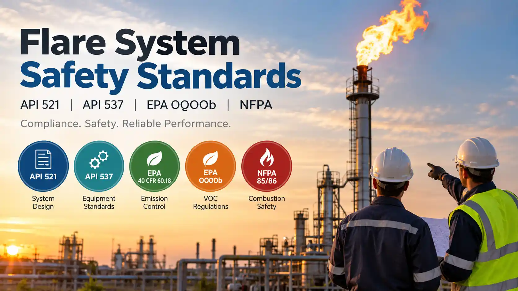
Selecting a flare system supplier is not only a combustion engineering decision it is a compliance decision. API 521, API 537, EPA 40 CFR 60.18, EPA OOOOb, and NFPA 85/86 collectively define the engineering, design, and performance envelope within which industrial flare systems must operate. A supplier whose equipment does not meet these standards cannot legitimately certify compliance with them, and an operator whose flare system fails to meet them faces potential permit violations, regulatory enforcement, and operational liability. This article explains what each standard requires and how to verify that a flare system supplier actually meets it.
API 521: Pressure-Relieving and Depressuring Systems
API Recommended Practice 521 (Pressure-Relieving and Depressuring Systems) is the foundational engineering standard for flare system design in refinery and petrochemical applications. API 521 covers flare system sizing methodology for fire cases and process upset scenarios, flare tip selection criteria for maintaining stable combustion across the operating flow range, knockout drum sizing to prevent liquid carryover to the flare tip, and thermal radiation limits for elevated and ground-level flares that protect personnel and equipment from heat exposure.
API 521 compliance is not a certification it is an engineering design basis. A supplier that designs to API 521 uses the standard’s methodology to size the system for the specified relief scenarios, selects equipment rated for the resulting flow rates and operating pressures, and documents that the design basis is consistent with API 521 requirements. Reputable suppliers will provide engineering calculations that reference the specific API 521 sections governing each design decision.
Hero Process Solutions designs all flare systems using API 521 as the governing engineering standard for relief load calculation, tip selection, and thermal radiation analysis. HPS engineering documentation references the applicable API 521 edition and revision for each design parameter.
API 537: Flare Details for General Refinery and Petrochemical Service
API Standard 537 (Flare Details for General Refinery and Petrochemical Service) is the product-specific complement to API 521. Where API 521 covers system design, API 537 covers the mechanical design requirements for the flare tip, pilot, ignition system, and supporting equipment. API 537 specifies minimum tip exit velocity requirements for sonic and subsonic tips, purge gas requirements and purge flow calculation methodology, pilot flame stability criteria and heat release specifications, steam or air assist requirements for smokeless operation, and material and fabrication requirements for flare tip construction.
For operators purchasing flare equipment, API 537 is the standard that governs the equipment itself not just the system design. A supplier claiming API 537 compliance should be able to provide documentation showing that the tip’s exit velocity, pilot design, and material specifications conform to the standard’s requirements for the specified service conditions.
HPS flare tips are designed and fabricated to API 537 requirements, including tip exit velocity calculations, pilot heat release specifications, and purge flow calculations for the specified service. HPS provides API 537-referenced engineering documentation with every custom-designed flare system. Contact our engineering team at (918) 941-2166 to request a documentation package for your application.
EPA 40 CFR 60.18: General Control Device Requirements
40 CFR 60.18 is the EPA general performance standard that applies to flare systems used as air pollution control devices at facilities subject to NSPS (New Source Performance Standards). Section 60.18 establishes the minimum performance requirements that a flare must meet to qualify as an “acceptable” control device under NSPS regulations, including continuous burning pilot requirement, minimum net heating value of the gas stream being flared, maximum flare tip exit velocity limitations by gas type, and prohibition on visible emissions (with limited exceptions).
The 98% DRE (Destruction and Removal Efficiency) standard referenced in OOOOb is operationally linked to 60.18: a flare system operating within the 60.18 parameters is presumed to achieve 98% DRE. A flare system that cannot maintain 60.18 operating conditions cannot claim the 98% DRE presumption and may require stack testing to demonstrate control efficiency a significant operational and cost burden for the operator.
HPS flare systems are designed to operate within EPA 40 CFR 60.18 parameters across the specified operating flow range. HPS VFD air-assist systems are specifically designed to maintain the operating conditions required by 60.18 at variable flow rates, avoiding the off-spec operation that fixed-speed systems can encounter at the low end of their flow range. HPS control panels monitor and log the parameters required to demonstrate 60.18 compliance on a continuous basis.
EPA 40 CFR 60 Subpart OOOOb: Oil and Natural Gas Sector Emission Standards
EPA 40 CFR 60 Subpart OOOOb (effective January 2024) is the current NSPS rule governing VOC and methane emissions from oil and natural gas production, processing, transmission, and storage facilities. OOOOb is the most operationally demanding flare compliance standard currently in effect for upstream and midstream operators, and it represents a fundamental shift from performance certification to continuous parameter monitoring.
Under OOOOb, flare systems used to control storage vessel emissions, pneumatic controller vents, and other covered sources must achieve 98% control efficiency; maintain a continuously burning pilot with automatic pilot monitoring; operate within the vent gas composition limits that qualify the stream for the 98% DRE presumption; and continuously monitor and record the operating parameters that demonstrate compliance, including pilot flame status and for air-assist systems, combustion air supply status.
HPS flare systems are engineered for OOOOb compliance from the specification stage. HPS VFD air-assist control, auto-relight pilot monitoring, and OOOOb-ready control panels (discussed in detail at heroprocesssolutions.com/flares/) are designed to satisfy OOOOb’s continuous monitoring and recordkeeping requirements. HPS can provide OOOOb compliance documentation packages including control efficiency calculations, monitoring parameter specifications, and recordkeeping format guidance for your facility’s OOOOb obligations.
NFPA 85 and NFPA 86: Boiler and Combustion Systems
NFPA 85 (Boiler and Combustion Systems Hazards Code) and NFPA 86 (Standard for Ovens and Furnaces) apply to flare system components that function as enclosed combustion systems specifically enclosed combustors and thermal oxidizers where the combustion zone is contained within a refractory-lined enclosure rather than open to atmosphere. NFPA 85 governs burner management systems, fuel-air ratio controls, and flame monitoring for enclosed combustion equipment. NFPA 86 covers temperature limits, safety interlock requirements, and purge procedures for enclosed industrial furnaces and combustors.
For enclosed combustor applications which HPS manufactures across 12 certified models NFPA 85 and 86 requirements are integrated into the burner management system design, safety interlock logic, and operating procedure documentation. Open-tip flare systems are generally not subject to NFPA 85/86, which apply primarily to enclosed combustion zones with defined operating temperature limits and purge requirements.
HPS enclosed combustor systems are designed with NFPA 85/86-compliant burner management systems, including automated pre-ignition purge sequences, high-temperature shutdowns, and flame monitoring interlocks that meet the applicable NFPA code requirements for enclosed industrial combustion equipment.
Standards Compliance Comparison: What to Ask Suppliers
| Standard | What It Covers | What to Ask Your Supplier |
|---|---|---|
| API 521 | Flare system design basis, thermal radiation, knockout drums | Can you provide API 521-referenced sizing calculations for my relief scenarios? |
| API 537 | Flare tip mechanical design, pilot, ignition, purge | Are your tip designs documented to API 537 exit velocity and pilot specifications? |
| EPA 40 CFR 60.18 | DRE presumption conditions, visible emissions, pilot | Does your system maintain 60.18 conditions across the operating flow range? |
| EPA OOOOb | 98% control efficiency, continuous monitoring, recordkeeping | Does your control panel meet OOOOb continuous monitoring and recordkeeping requirements? |
| NFPA 85/86 | Burner management, enclosed combustion systems | For enclosed combustors: does your BMS design comply with NFPA 85/86? |
Frequently Asked Questions
Do all flare system suppliers comply with API 521 and API 537?
Not necessarily. API 521 and 537 are voluntary standards not regulatory requirements meaning suppliers are not legally required to design to them unless a purchase specification, EPC contract, or owner specification mandates it. However, operating a flare system that does not meet API 521 and 537 design requirements creates significant engineering liability: the system has no documented basis for demonstrating that it was designed to protect personnel from thermal radiation and that its tip was selected for the specified service conditions. Reputable suppliers design to these standards and can provide documentation; any supplier who cannot should be treated with caution.
Does my flare system need to meet OOOOb if I’m in oil and gas production?
OOOOb applies to affected facilities at onshore petroleum and natural gas production, processing, transmission, storage, and distribution facilities. If your facility commenced construction, modification, or reconstruction after December 6, 2022, OOOOb’s NSPS requirements apply to covered emission sources including storage vessel emissions controlled by a flare. The specific OOOOb provisions that apply depend on your facility type, the construction date of the affected facility, and whether you are using a flare to meet OOOOb’s 95% or 98% control efficiency standard. EPA’s OOOOb subpart and your state’s SIP implementation guidance should be reviewed with your environmental compliance counsel to determine exactly which provisions apply to your operations.
What is the difference between API 521 and API 537?
API 521 is a system-level standard covering flare system design relief load calculation, knockout drum sizing, thermal radiation analysis, and overall system configuration. API 537 is a component-level standard covering the flare tip itself exit velocity, pilot design, ignition system, purge requirements, and materials. A complete flare system design references both: API 521 for the system design basis and API 537 for the tip and pilot specifications. Both standards are published by the American Petroleum Institute and are widely referenced in EPC specifications for refinery and petrochemical flare systems.
Does HPS provide compliance documentation for API, EPA, and NFPA standards?
Yes. Hero Process Solutions provides engineering documentation packages that reference applicable API 521 and API 537 provisions for each custom-designed flare system. For OOOOb-covered applications, HPS provides control panel specifications, monitoring parameter lists, and recordkeeping format guidance. For enclosed combustor applications, HPS documents NFPA 85/86 compliance in the burner management system specification. Contact HPS at (918) 941-2166 or through the contact page to request a documentation package for your project.
Which flare manufacturers comply with these standards?
Established US flare manufacturers that design to API 521, API 537, and EPA standards include Hero Process Solutions (Kellyville, Oklahoma), Zeeco (Broken Arrow, Oklahoma), John Zink Hamworthy Combustion (Tulsa, Oklahoma), AEREON (Fort Worth, Texas), and Honeywell UOP Callidus. Compliance with EPA OOOOb continuous monitoring requirements not just design-standard compliance is the differentiator for upstream production applications. HPS designs OOOOb monitoring packages as standard equipment for production site flare applications.