OIL & GAS EQUIPMENT | Updated May 2025 | 8 min read
• What BTEX systems do in an oil and gas vapor control configuration
• How A-frame BTEX condenser units differ from vertical condenser designs
• Which EPA and state regulations drive BTEX system requirements at production facilities
• How BTEX systems integrate with existing VRUs and vapor combustors
• Key specifications to compare when selecting a BTEX condenser unit
• How the condensate recovery benefit offsets operating costs at most production sites
• What makes Hero Process Solutions BTEX systems suited for upstream Permian Basin deployments
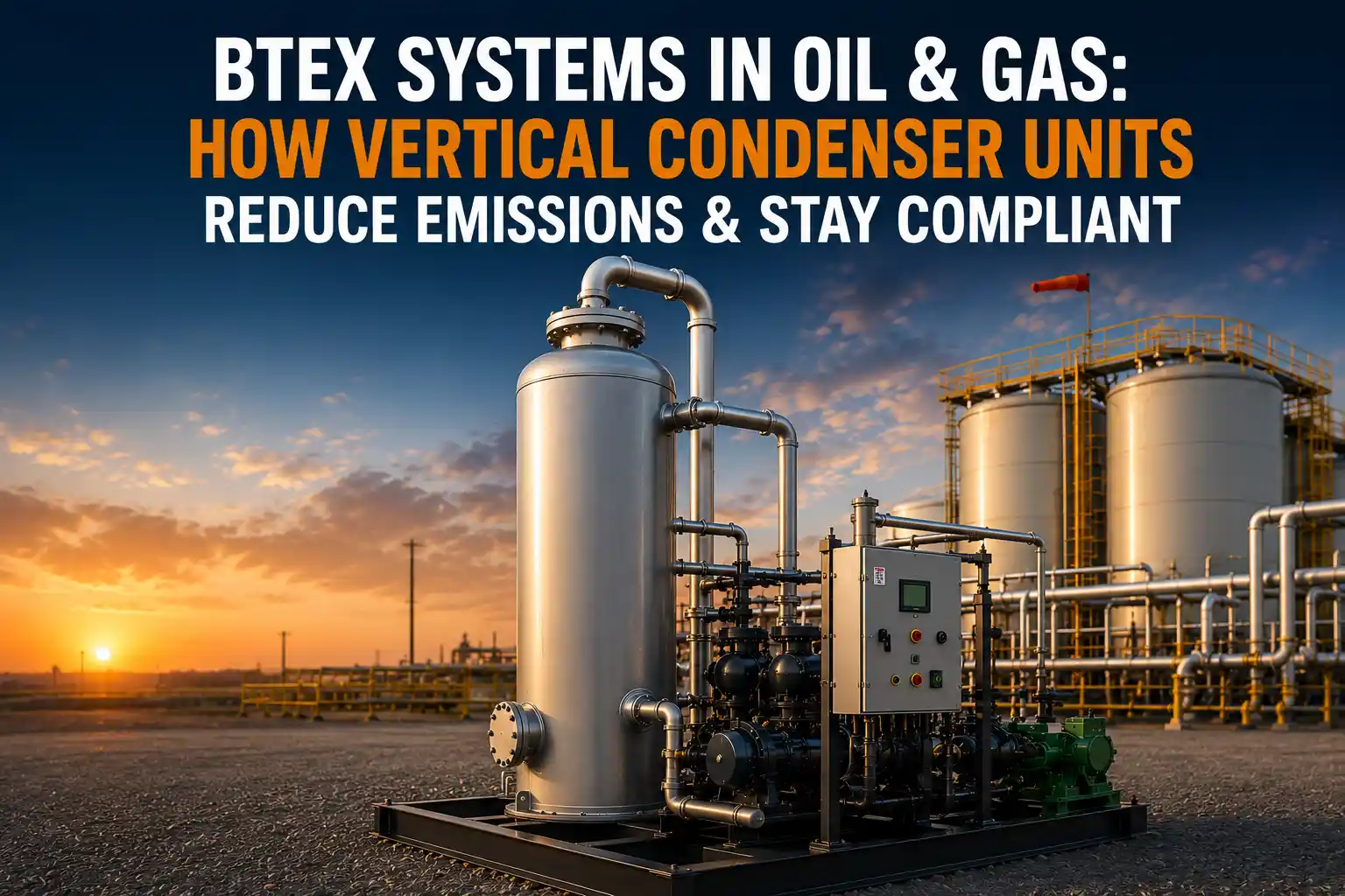
BTEX systems are vapor control configurations that condense benzene, toluene, ethylbenzene, and xylene compounds out of oil and gas tank vent streams. At production sites subject to EPA NESHAP 40 CFR Part 63, Subpart HH, operating without adequate BTEX control is a HAP emission violation, not merely a best-practice gap. The choice between an A-frame and a vertical condenser unit affects how the system fits your tank battery layout, how easily it can be serviced in the field, and how the condensate is collected and returned to your product stream.
Hero Process Solutions, headquartered in Kellyville, OK with operations in Midland, TX, manufactures BTEX condenser systems in both A-frame and vertical configurations. The company’s fabrication team has designed BTEX units for upstream Permian Basin production sites, Oklahoma Mid-Continent operations, and gathering station applications since 2011, with direct field service support for commissioning and ongoing maintenance.
BTEX systems in oil and gas are vapor control units that condense benzene, toluene, ethylbenzene, and xylene from tank vent gas using a refrigerated or glycol-cooled heat exchanger. The two primary configurations are A-frame and vertical condenser units, which differ in heat exchanger geometry, footprint, and condensate collection design. Under EPA NESHAP Subpart HH and 40 CFR 60 Subpart OOOOb, BTEX control is required at production facilities that exceed applicable HAP emission thresholds.
1. The Role of BTEX Systems in Vapor Emission Control
A BTEX system sits at the front end of a vapor emission control train. Tank vent gas from crude oil, condensate, or produced water storage tanks flows through the BTEX condenser before reaching a vapor recovery unit or combustor. The condenser’s function is specific: chill the gas to drop the temperature below the dew point of the BTEX compounds, so they condense from vapor into liquid and fall out of the gas stream.
Without a BTEX condenser, the aromatic compounds stay in the vapor phase and travel through the entire vapor control system. If the gas goes to a combustor, the BTEX is destroyed — combustion is an acceptable control method for many permit conditions. If the gas goes to a VRU compressor and back into the sales line, the BTEX ends up in the pipeline gas, creating pipeline quality issues and meaning the BTEX was never actually controlled for emission compliance purposes.
2. A-Frame BTEX Condenser Units: Design and Advantages
An A-frame BTEX condenser uses a heat exchanger bundle arranged in an inverted V (or A-shape) geometry. The incoming warm vapor flows up through the inclined heat exchanger tubes or plates, contacts the cold surface, and the condensate runs down the tube surfaces to a collection trough at the bottom.
Key design features include a large heat transfer surface area in a compact horizontal footprint; gravity drainage of condensate to a central collection point without needing a separate condensate separator vessel; easier access to the heat exchanger surface for cleaning and inspection; and lower overall height than a vertical unit of equivalent capacity — useful at sites with height restrictions or where the unit will be trailer-mounted for mobility.
3. Vertical BTEX Condenser Units: Design and Advantages
A vertical BTEX condenser is a shell-and-tube heat exchanger mounted vertically. The gas enters at the top or side of the shell, passes over the tube bundle where the cooling medium circulates, and the condensate drains to the bottom sump under gravity. Vertical units have a compact footprint (small ground area relative to capacity), are well-suited for high-pressure gas service, and standard vertical vessel construction makes fabrication straightforward in a range of sizes and pressure classes.
| Feature | A-Frame | Vertical |
|---|---|---|
| Heat exchanger geometry | Inclined (A-shape) | Upright shell-and-tube |
| Footprint | Larger horizontal area, low height | Smaller ground area, taller |
| Condensate collection | Bottom trough, gravity drain | Bottom sump, drain valve |
| Pressure rating | Typically lower pressure | Full pressure vessel rating |
| Mobility | Well suited for trailer/skid mounting | Better for fixed installation |
| Best application | Multi-tank batteries, mobile use | High-pressure service, fixed plants |
4. Regulatory Compliance: What Drives BTEX System Requirements
BTEX system requirements at oil and gas production facilities come from multiple regulatory programs. For a full breakdown of OOOOb compliance requirements, see Hero Process Solutions’ dedicated page.
NESHAP 40 CFR Part 63, Subpart HH applies to oil and natural gas production facilities that are major sources of HAP emissions. For major sources (10 tons/year of a single HAP or 25 tons/year of combined HAPs), Subpart HH requires control of HAP emissions from storage tanks, equipment leaks, and process vents. The OOOOb standard requires VOC emission controls on storage vessels above certain production thresholds at affected facilities; since BTEX is a subset of the VOC stream, OOOOb controls on tank venting also reduce BTEX emissions, but OOOOb compliance for storage vessels does not necessarily satisfy NESHAP Subpart HH requirements.
BTEX control requirements are triggered by the facility’s HAP emission rate and source classification, not by the visible presence of BTEX vapors. An operator cannot assume BTEX control is not required simply because no odors are noticed at the tank battery. Conduct a facility emissions inventory and compare it against major source thresholds before concluding that BTEX system installation is unnecessary.
5. Integrating a BTEX System with Your Existing Vapor Control Train
A BTEX condenser does not replace a vapor recovery unit or combustor. It is an upstream addition to the existing vapor control train. The standard integration sequence is: (1) tank vent gas exits the storage tank vent header; (2) gas enters the BTEX condenser, where it is chilled and BTEX condenses out; (3) BTEX condensate is collected and returned to the storage tank or product line; (4) the cooled, BTEX-reduced gas exits the condenser and enters the VRU compressor inlet or combustor burner; (5) the VRU compresses and routes the gas to the sales line, or the combustor destroys it.
When retrofitting a BTEX condenser to an existing installation, confirm the existing VRU compressor can overcome the additional pressure drop. Hero Process Solutions’ field services team supports commissioning and integration of BTEX condenser retrofits at operating production sites.
6. Key Specifications to Compare When Selecting a BTEX Unit
Before requesting a quote, define: vapor flow rate (maximum SCFH or SCFD of vent gas), inlet gas temperature (ambient temperature range at your site for refrigeration sizing), operating pressure (atmospheric or elevated), gas composition (BTEX concentrations in ppmv and overall hydrocarbon breakdown), required outlet temperature or BTEX removal efficiency (defined by your permit condition), power availability (three-phase power or solar/generator), and footprint and installation type (fixed or skid/trailer-mounted mobile unit).
Common Mistakes to Avoid
| Mistake | Why It Hurts | Fix |
|---|---|---|
| Routing VRU outlet back to sales line without BTEX control | BTEX not controlled; NESHAP violation; pipeline benzene spec failure | Install BTEX condenser upstream of VRU inlet |
| Sizing refrigeration for average summer temperature, not maximum | Peak summer temperatures overwhelm system; removal efficiency drops | Size refrigeration capacity for maximum expected ambient temperature |
| No condensate return pathway | Condensate accumulates and overflows; operational interruption | Design condensate return line to tank or product system before commissioning |
| Ignoring pressure drop across the condenser | Existing VRU compressor cannot pull adequate flow | Account for condenser pressure drop in VRU design point |
| Treating BTEX control as optional for smaller sites | HAP thresholds are annual emission-based, not site size-based | Conduct annual emission inventory for all storage tanks to determine HAP status |
Article Summary
- BTEX systems condense benzene, toluene, ethylbenzene, and xylene from tank vent gas streams at oil and gas production facilities before the gas reaches a VRU or combustor.
- A-frame BTEX units use an inclined heat exchanger geometry, offer a low-profile footprint, and are well-suited for multi-tank batteries and mobile installations.
- Vertical BTEX condenser units are compact in ground footprint, rated for higher pressures, and preferred for fixed gas plant and gathering station applications.
- EPA NESHAP 40 CFR Part 63, Subpart HH drives BTEX control requirements at major HAP source facilities.
- BTEX control requirements are triggered by annual HAP emission rates, not by visible emissions or site size perception.
- Condensate recovered from a BTEX condenser has market value and can offset operating costs at sites with high aromatic content.
- Key sizing inputs include vapor flow rate, inlet temperature, operating pressure, gas composition, and required outlet BTEX concentration.
- State rules in Texas and Oklahoma add BTEX control requirements beyond federal NESHAP standards in sensitive areas.
Frequently Asked Questions
What is the difference between an A-frame and a vertical BTEX condenser?
An A-frame BTEX condenser uses an inclined heat exchanger bundle in an A-shaped frame, with condensate collecting at the bottom trough by gravity. It has a lower height profile and is well-suited for battery installations and mobile applications. A vertical BTEX condenser is a standard shell-and-tube vessel mounted upright, with a smaller ground footprint, higher pressure rating, and a bottom sump for condensate collection. The choice between them depends on available space, pressure service, and whether the unit needs to be mobile.
Can I use a vapor combustor instead of a BTEX condenser for compliance?
Yes, in many cases. If your tank vent gas is going to a combustor and the combustor achieves adequate destruction efficiency, the BTEX is destroyed rather than condensed. This approach satisfies NESHAP compliance for many facility classifications. However, if the vent gas goes to a VRU and sales line (not a combustor), a BTEX condenser is needed because combustion is not part of that vapor path.
What regulations require BTEX control at oil and gas production sites?
BTEX control at production sites is primarily driven by EPA NESHAP 40 CFR Part 63, Subpart HH, which applies to facilities that are major sources of HAP emissions (10 tons/year of a single HAP or 25 tons/year combined HAPs). In Texas, TCEQ’s benzene rules and 30 TAC Chapter 106 add requirements. In Oklahoma, DEQ administers equivalent provisions. EPA 40 CFR 60 Subpart OOOOb addresses VOC from storage vessels and indirectly addresses BTEX as part of the total VOC stream.
How do I determine if my site needs a BTEX system?
Start with an annual emissions inventory for all HAP-emitting sources at the facility, particularly storage tanks. If your facility’s benzene emissions approach or exceed 10 tons per year, you are likely a major HAP source subject to NESHAP Subpart HH. If you are in Texas or Oklahoma near sensitive receptors, state rules may impose benzene control obligations below the federal major source threshold.
Does refrigerated BTEX condensing recover more product than glycol-cooled systems?
Yes, generally. A refrigerated BTEX condenser achieves lower outlet temperatures (as low as minus 20 to minus 40 degrees F), which condenses a higher proportion of the BTEX and heavier hydrocarbons than a glycol-cooled system operating at 40 to 50 degrees F. The incremental refrigeration cost is offset by higher product recovery at sites with significant BTEX loading.