Not all flare tips perform the same. The difference between a standard open-pipe tip and a modern sonic design affects your smokeless capacity, your EPA compliance posture, your radiation footprint, and the long-term cost of operating your flare system.
This article breaks down exactly how sonic flare tips differ from conventional designs, where each type belongs, and what measurable efficiency gains you can expect when pressure conditions support the switch.
What Makes a Standard Flare Tip
The term ‘standard flare tip’ in industrial practice most often refers to an open-pipe or utility-grade tip. These are straight-pipe or slightly profiled tips where gas exits at a single point without any mechanism to increase air entrainment or turbulence. They are simple, inexpensive, and effective for applications where smokeless performance is not required — typically emergency relief of light, clean gases with high net heating values.
Standard utility tips are designed to handle the maximum emergency release flow without catastrophic tip burnback. They do this job reliably. But they produce visible smoke when burning heavier hydrocarbons, and they offer no turndown smokeless capability. At low flow rates, exit velocity drops and combustion becomes incomplete.
According to ScienceDirect engineering reference material on flare systems, standard open-pipe tips are not sized for smokeless operation — they are sized for maximum flow velocity at the design release rate, with smokeless performance considered a secondary objective addressed separately through steam or air injection.
What Makes a Sonic Flare Tip Different
A sonic flare tip is a purpose-engineered combustion device that uses the pressure energy in the waste gas stream to achieve high exit velocity, turbulent mixing, and — in the best designs — self-regulating air entrainment. The distinguishing design elements include:
Convergent nozzle geometry: Rather than an open pipe, sonic tips use precisely shaped nozzles or annular slots designed to accelerate gas to sonic velocity at the exit point. This produces the turbulent mixing zone that draws ambient air into the combustion envelope.
Multi-point or multi-arm configurations: Many sonic tip designs distribute gas to multiple smaller-diameter exit points arranged around a central body. This creates multiple smaller flames rather than one large flame, which reduces radiation, improves mixing uniformity, and extends smokeless turndown.
Coanda-effect air induction: The most advanced sonic tip designs incorporate a tulip-shaped Coanda body at each exit point. The curved surface of this body causes the exiting gas jet to follow its profile, drawing large volumes of ambient air into the combustion zone through fluid dynamics alone — no steam, no blowers, no utilities.
Variable orifice capability: High-performance Coanda sonic tips use an adjustable inner cone that changes the annular slot area as flow varies. This maintains exit velocity — and therefore smokeless performance — across a much wider range of operating flows than a fixed-orifice design can achieve.
Key Differences at a Glance
Smokeless capacity
Standard open-pipe tips have no inherent smokeless capacity when burning heavier hydrocarbons. Sonic tips are designed from the outset to achieve 100% smokeless combustion within their specified pressure range and without utility injection.
Turndown range
A standard tip has a fixed-diameter exit. As flow drops, exit velocity drops proportionally, and smokeless performance deteriorates. Variable-orifice Coanda sonic tips maintain exit velocity — and therefore air induction — across flow ranges of 300:1 or greater.
Utility consumption
Standard tips with smoke control require continuous steam or air injection. Sonic Coanda tips require no utilities under design conditions, which eliminates the operating cost and infrastructure associated with smoke suppression systems.
Combustion efficiency
Sonic Coanda tips achieve destruction and removal efficiency (DRE) of 98% or greater under design conditions. Standard open-pipe tips burning heavy hydrocarbons without assist typically achieve DRE values in the range of 85 to 95%, with significant variability at low flow rates.
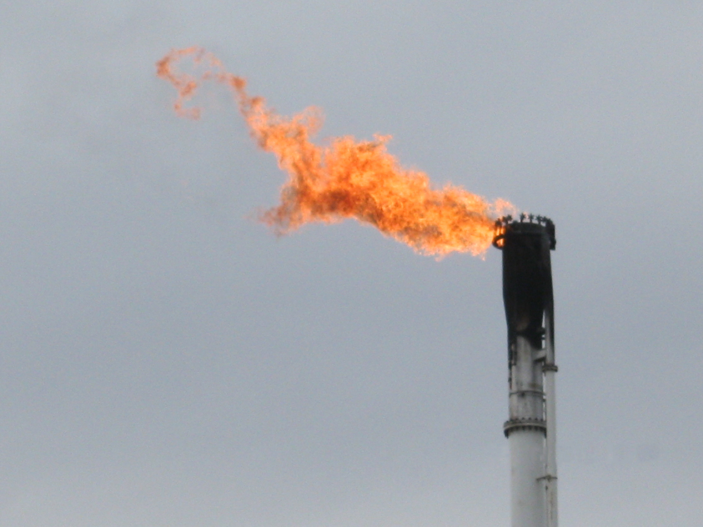
Flame length
Sonic tips produce shorter, more stable flames than open-pipe tips at equivalent flow rates. Shorter flames reduce thermal radiation at grade level, allow shorter stack heights, and are more resistant to wind-induced pull-down and flame instability.
Noise
Sonic flares operate at higher noise levels than sub-sonic open-pipe tips due to the high-velocity gas discharge. Research from the ACS Omega Permian Basin pilot study found that Coanda-effect sonic tip noise levels fell below the OSHA-recommended 85 dB threshold at distances of approximately 100 to 125 feet from the flare stack.
EPA compliance
Both tip types can be used in compliant flare systems, but sonic tips are designed to meet the net heating value and exit velocity requirements of 40 CFR 60.18 within a self-contained tip assembly. Standard tips may require additional infrastructure — steam rings, air injection, or blower systems — to achieve equivalent compliance.
Pressure-Assisted vs. Utility Blower Designs
One of the most practical decisions facility engineers face is whether to use a pressure-assisted sonic flare or an air-assisted flare with a blower. These two technologies are the dominant choices for new smokeless flare installations in upstream oil and gas, midstream processing, and refining applications.
Pressure-assisted sonic flares are the preferred choice when inlet gas pressure is consistently above 30 psig. The absence of rotating equipment — no blowers, no motors, no drive systems — simplifies maintenance, reduces failure modes, and eliminates power consumption for smoke control. Offshore platforms and remote production sites benefit most from this simplicity.
Air-assisted flare designs are appropriate when gas pressure is too low or too variable to sustain sonic velocity across the expected operating range. They provide reliable smokeless performance independent of gas pressure but require an ongoing supply of utility power for blower operation. For applications with low-pressure flare headers or gas compositions that require a controlled air supply, air-assisted flares remain the correct technical choice.
Where Each Technology Belongs
Upstream oil and gas production: Variable-orifice Coanda sonic tips are widely used on production separators, well test systems, and gathering facilities where operational flaring occurs regularly and pressure is available. Their ability to handle wide flow variability and liquid carryover makes them well suited to production environments. Reduced radiation levels are particularly valuable where deck layout constrains stack placement.
Midstream gas processing: Fixed-orifice multi-arm sonic tips are commonly applied in midstream compressor stations and gas plants, where inlet pressure is more consistent and flow rates follow predictable operational patterns.
Refining and chemical processing: Multi-point sonic systems are widely used in refinery flare headers, where the combination of large flow range and variable gas composition requires robust smokeless performance across all conditions.
Efficiency Gains in Practice
The efficiency gains from sonic flare tips are measurable in three categories:
Combustion efficiency: Sonic tips operating under Coanda-effect principles achieve DRE of 98% or greater, compared to typical DRE values of 85 to 95% for standard open-pipe tips burning heavy hydrocarbons without assist. This directly reduces VOC and methane emissions per unit of gas flared.
Operating cost: Eliminating steam injection or blower operation reduces energy consumption and maintenance costs. For large facilities with continuous operational flaring, the annual utility savings from a pressure-assisted sonic design compared to a steam-injected system can be substantial.
Structural cost: Shorter flames mean lower required stack heights to satisfy radiation limits. Reduced stack height translates to lower structural steel requirements, smaller foundations, and reduced wind load design criteria — particularly relevant for offshore applications.
Frequently Asked Questions
What minimum pressure do I need to specify a sonic flare tip?
Fixed-orifice sonic tips generally require 15 psig or more at the flare tip inlet. Variable-orifice Coanda designs typically need 30 psig minimum to maintain smokeless performance across the full operating range. Your flare gas pressure profile should be the basis for this decision.
Can I retrofit a sonic tip onto an existing open-pipe flare stack?
In many cases, yes. Sonic tip assemblies are available in standard pipe flange sizes that can be fitted to existing stacks. The key requirement is sufficient inlet pressure at the existing stack diameter. A review of your pressure profile and stack configuration will confirm whether a retrofit is feasible.
What minimum pressure do I need to specify a sonic flare tip?
Most sonic flare designs require a minimum of 15 psig at the flare tip inlet for standard fixed-orifice configurations, with variable slot Coanda designs typically needing 30 psig or more to maintain smokeless turndown across the full flow range. Gas composition also affects the minimum pressure threshold.
If you are evaluating tip technology for a new installation or a system upgrade, our engineering team can review your pressure profile, gas composition, and flow range to recommend the most reliable and cost-effective solution. Visit our flares page or contact us directly to start the conversation.