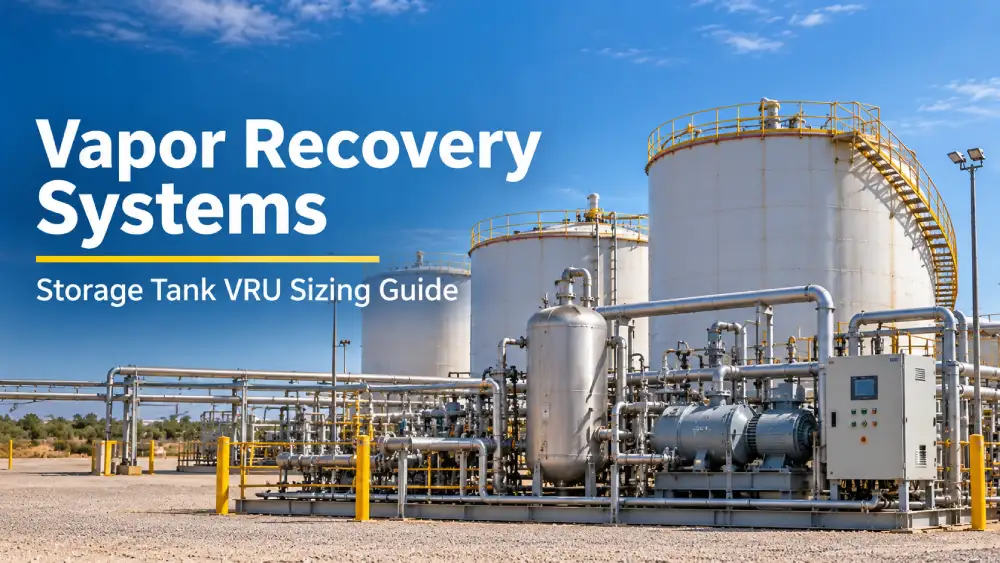

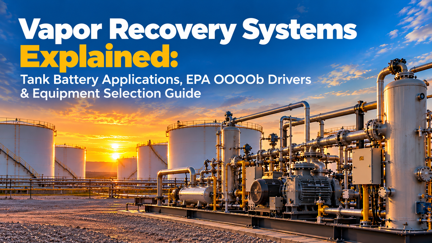
- How vapor recovery systems capture and route tank battery vent gas to a control device
- Which EPA 40 CFR 60 Subpart OOOOb emission thresholds trigger control requirements
- VRU vs. enclosed combustor vs. low-pressure flare: selection criteria for each
- When BTEX condenser systems are required to protect downstream equipment
- Key sizing inputs that determine correct system capacity
- Closed vent system design and inspection requirements under OOOOb
- The most common selection mistakes that lead to permit violations
Tank battery storage tanks in upstream oil and gas operations continuously release hydrocarbon vapors through working losses, thermal breathing cycles, and flash gas as produced fluids reach atmospheric conditions. A properly designed vapor recovery system intercepts those vapors at the tank dome vent and routes them to a control device that either recovers the gas for sale or destroys it through combustion. For producers operating new or modified upstream facilities subject to EPA 40 CFR 60 Subpart OOOOb, installing an approved vapor recovery system is a regulatory requirement tied directly to actual annual VOC emissions from each affected storage vessel.
Hero Process Solutions, headquartered in Kellyville, Oklahoma with field support extending to the Permian Basin and Gulf Coast, engineers and manufactures the combustion and vapor control equipment that forms the back end of most vapor recovery systems. The product line includes enclosed vapor combustors rated from 0.1 to 10 MMBtu/hr, BTEX condenser systems for upstream and midstream service, low-pressure flares for tank battery vent applications, and packaged field commissioning and inspection services. Founded in 2011, Hero Process Solutions has supplied vapor control equipment across production, midstream, gas processing, and refinery sectors worldwide.
A vapor recovery system is a collection of equipment, including closed vent piping, upstream liquid conditioning, and a primary control device, that captures hydrocarbon vapors from crude oil, condensate, and produced water storage tanks and routes them to a vapor recovery unit (VRU), enclosed combustor, or compliant low-pressure flare. Under EPA 40 CFR 60 Subpart OOOOb, affected storage tanks at new and modified upstream oil and gas facilities must control VOC emissions to a minimum 95% reduction efficiency using an approved control device. Equipment selection depends on vent gas rate, stream composition, BTEX content, available pressure, and whether gas-to-sales economics support compression and treatment.
1. How Vapor Recovery Systems Work in Tank Battery Applications
Storage tank vapor losses occur through three mechanisms. Working losses happen when liquid enters the tank and displaces vapor-saturated gas through the vent connection. Thermal breathing losses result from daytime heating expanding vapor space gas until it vents at the pressure-vacuum valve setting. Flash losses are the highest-rate source in high-GOR crudes: produced fluids carrying dissolved gas release that gas as pressure drops from separator conditions to atmospheric.
A vapor recovery system collects these vapor streams through a closed vent header connected to each tank dome vent, thief hatch, and pressure-vacuum valve outlet in the battery. A liquid knockout pot upstream of the primary control device removes entrained droplets before the gas enters the compressor, combustor, or flare. For high-GOR or high-BTEX streams, an upstream BTEX condenser system removes heavier aromatics and NGLs that would otherwise foul compressor internals or coat combustor burner tips with coke deposits.
Flash losses are typically the dominant vapor source in crude oil storage. A gas-oil ratio above 300 scf/bbl at separator conditions is a reliable indicator that a BTEX condenser or inlet chiller will be required to protect the primary control device from liquid carryover and aromatic fouling.
2. EPA OOOOb Applicability: Which Storage Tanks Require Vapor Recovery?
Under 40 CFR Part 60 Subpart OOOOb, a crude oil, condensate, or produced water storage tank becomes an “affected facility” when two conditions are met: (1) the tank is located at an upstream oil and gas facility that commenced construction, reconstruction, or modification after December 6, 2022, and (2) the tank’s actual annual average VOC emissions equal or exceed the applicable threshold, which is 6 tpy for crude oil and condensate tanks at most upstream facility types.
Compliance requires routing vent gas through a closed vent system to an approved OOOOb control device that achieves 95% or greater VOC reduction. Approved control pathways include a vapor recovery unit with documented sales line acceptance, an enclosed combustor with a minimum 98% destruction removal efficiency (DRE), or an open flare meeting the performance parameters of 40 CFR 60.18. The rule additionally requires an initial closed vent system inspection within 30 days of startup and annual follow-up inspections using optical gas imaging (OGI) cameras or EPA Method 21 instruments.
State-level regulations in Texas (30 TAC Chapter 115), New Mexico (20.2.50 NMAC), and Colorado (5 CCR 1001-9 Regulation 7) may impose stricter thresholds or earlier compliance deadlines than the federal OOOOb standard. Operators should review the applicable state implementation plan alongside the federal rule before committing to a control device type.
3. Control Device Types in a Vapor Recovery System
Three primary control device types are deployed in upstream vapor recovery systems. The correct choice depends on vent gas rate, stream quality, commodity value, available infrastructure, and the operator’s OOOOb compliance pathway.
Vapor Recovery Units (VRUs)
A VRU is a compressor package, typically using a reciprocating or rotary screw compressor, that draws vent gas from tank dome vents at near-atmospheric pressure, compresses it to sales line or fuel gas pressure, and delivers it downstream for sale or reuse. VRUs provide the strongest economic return for facilities with saleable gas quality and vent rates above approximately 0.1 MMscfd. They satisfy OOOOb through demonstrated gas-to-sales acceptance rather than through a combustion efficiency standard, so upstream gas conditioning to meet pipeline spec is often required.
Enclosed Vapor Combustors (VCUs)
A vapor combustor unit burns tank vent gas in a refractory-lined enclosed firebox, achieving 98%+ VOC DRE without a visible flame. Combustors are the standard OOOOb compliance path when gas-to-sales is not viable because gas quality is off-spec (high H2S, high CO2, or high nitrogen content), vent rates are below compression economics, or surface lease agreements prohibit visible flames. Hero Process Solutions’ enclosed combustors are configurable for high-BTEX and sour service across the 0.1 to 10 MMBtu/hr thermal input range.
Low-Pressure Flares
A low-pressure flare handles vent gas at the 2 to 14 inches water column pressures typical of tank dome vent connections, providing an open-flame combustion pathway for low-rate applications. LP flares are most useful as backup control devices behind a VRU during compressor downtime, or as the primary device on very low-rate pads where the capital cost of a packaged combustor is not justified. Under OOOOb, the flare must comply with 40 CFR 60.18, including net heating value above 300 BTU/scf, auto-relight pilot with thermocouple or UV sensor flame confirmation, and exit velocity limits.
For multi-tank batteries where a VRU provides the primary vapor recovery function, a backup combustor or LP flare is strongly recommended to maintain OOOOb compliance during compressor downtime or scheduled maintenance. EPA OOOOb does not provide a compliance exemption for unplanned or planned equipment outages.
4. VRU vs. Enclosed Combustor vs. LP Flare: Selection Guide
Selecting the right primary control device involves weighing gas rate, stream quality, commodity value, regulatory deadline, and capital budget. The table below compares the three main options for upstream tank battery vapor recovery service.
| Factor | Vapor Recovery Unit (VRU) | Enclosed Combustor (VCU) | LP Flare |
|---|---|---|---|
| Typical gas rate range | 0.1 to 5 MMscfd | 0.05 to 2 MMscfd | 0.01 to 0.5 MMscfd |
| Gas-to-sales potential | Yes (primary purpose) | None (gas destroyed) | None (gas destroyed) |
| VOC destruction efficiency | N/A (recovers gas) | 98%+ DRE | 98% per 40 CFR 60.18 |
| Sensitivity to BTEX / liquids | Requires upstream conditioning | Moderate tolerance | Low tolerance |
| OOOOb compliance pathway | Yes, via sales acceptance | Yes, via DRE standard | Yes, via 40 CFR 60.18 |
| Visible flame | None | None (enclosed) | Yes |
| Capital cost (relative) | Moderate to high | Moderate | Low to moderate |
| Backup device recommended? | Yes | No | No |
5. Sizing a Vapor Recovery System: Key Input Variables
Undersizing a vapor recovery system results in tank overpressure and thief-hatch venting during peak flash events, which generates both permit violations and visible emissions during field inspections. Oversizing wastes capital and creates turndown problems at low-production pads. Accurate sizing requires the following engineering inputs.
Peak flash gas rate, expressed in Mcfd or MMscfd, is the primary sizing driver. This is derived from stock tank flash calculations using wellhead or separator PVT data for the crude oil or condensate stream, not from simple separator gas volume estimates. Gas composition, including BTEX content, H2S concentration, and C6+ fraction, determines whether upstream conditioning is required and sets the materials specification for the control device. Available vent pressure at the tank dome, typically 4 to 12 inches of water column, governs compression ratio requirements for VRU sizing and inlet design parameters for combustors and flares. For multi-tank batteries, the peak coincident flash rate across all tanks on the header must be modeled, not simply summed at maximum individual rates. Hero Process Solutions’ field services engineering team performs flash rate calculations from wellhead samples or submitted compositional analyses as part of pre-project sizing assessments.
Sizing to average flash rate rather than the true maximum flash rate is the single most common engineering error in new vapor recovery installations. Use the maximum daily flash rate plus a 20% safety margin for control device inlet capacity. Failure to account for peak conditions during hot weather or after facility turnarounds leads to thief-hatch emissions events precisely when operators are most visible to inspectors.
6. BTEX Condenser Systems as an Upstream Vapor Recovery Component
BTEX condenser systems are heat exchangers placed upstream of the primary VRS control device to remove heavier aromatic compounds (benzene, toluene, ethylbenzene, and xylene) and higher-boiling NGLs from the tank vent gas stream before it reaches a compressor, combustor, or flare tip. High BTEX content causes compressor valve fouling, piston ring degradation, and lubricant contamination in VRUs. In combustors, entrained liquid BTEX droplets cause burner tip coking and unstable combustion that can degrade DRE below the 98% OOOOb threshold. In LP flares, liquid carryover produces visible smoke and reduces combustion efficiency.
Hero Process Solutions designs BTEX condenser systems in A-frame horizontal tube bundle and vertical shell-and-tube configurations. Ambient air-cooled A-frame units are the most common upstream choice for their low operating cost, minimal footprint, and absence of external cooling utilities. The condensate recovered flows by gravity or pump to the oil sales tank, providing a direct revenue offset against the system’s capital cost. Standard A-frame configurations handle 0.25 to 3 MMscfd vent gas throughput. The closed vent header between the tank dome vents and the BTEX condenser inlet should include a liquid knockout pot to intercept bulk liquid slugs before the condenser tube bundle.
7. Closed Vent System Requirements Under OOOOb
A vapor recovery system is only as effective as the closed vent system (CVS) that routes emissions from the tank to the control device. Under OOOOb, the CVS must be designed and maintained to prevent fugitive releases. All tank dome vents, thief hatches, pressure-vacuum valves, and open-ended lines must be connected to the closed vent header and operated at negative pressure relative to atmospheric whenever the control device is running. Bypass valves must be documented in a monitoring log and maintained in a car-sealed or locked-closed position during normal operations.
Initial CVS inspection must be conducted within 30 days of startup, and annual re-inspections are required using optical gas imaging cameras or EPA Method 21 portable instruments. Any thief hatch not plumbed into the CVS constitutes an uncontrolled emissions pathway that invalidates OOOOb compliance for the associated control device. An open thief hatch or failed pressure-vacuum valve found during an inspection will result in a notice of violation even if the flare or combustor control device is operating correctly. Hero Process Solutions’ vapor recovery system packages include closed vent header engineering as part of the standard project scope.
Under 40 CFR 60 Subpart OOOOb, a storage tank that bypasses its closed vent system or that has an open thief hatch not connected to the vapor collection header is in violation regardless of whether the downstream control device meets its destruction efficiency standard. CVS integrity is not optional — it is a separate compliance obligation from control device performance.
8. Regulatory Compliance Summary: 40 CFR 60 Subpart OOOOb for Storage Tanks
The following table summarizes the core OOOOb obligations for upstream storage tanks. Operators should review the full rule text at the EPA OOOOb resource page and consult legal counsel or a compliance specialist for facility-specific applicability determinations.
| OOOOb Requirement | Applicability Trigger | Standard |
|---|---|---|
| VOC control for crude/condensate tanks | Actual annual avg. VOC at or above 6 tpy at new/modified upstream facility | 95% VOC reduction; closed vent system required |
| Control device DRE (combustor) | Any affected tank controlled via enclosed combustor | 98% destruction removal efficiency |
| Flare performance standard | Any affected tank controlled via open flare | 40 CFR 60.18 (NHV greater than 300 BTU/scf, auto-relight pilot, exit velocity limits) |
| CVS initial inspection | All affected facilities at startup | OGI or EPA Method 21 within 30 days of startup |
| CVS re-inspection | All affected facilities in operation | OGI or EPA Method 21 at least annually |
| VRU compliance documentation | VRU used as primary control device | Demonstration of gas-to-sales or fuel gas acceptance |
9. Common Vapor Recovery System Selection Mistakes
| Mistake | Consequence | Correct Approach |
|---|---|---|
| Sizing to average flash rate only | Thief-hatch venting during peak events; OOOOb violation | Use maximum daily flash rate plus 20% safety margin |
| Skipping BTEX conditioning on high-GOR crude | Compressor fouling, combustor coking, smoke from LP flare | Run flash composition calculation; specify BTEX condenser if C6+ exceeds 1-2 mol% |
| Installing open flare without auto-relight pilot | Unlit flare vents gas without combustion; OOOOb non-compliance | Specify auto-relight pilot with thermocouple or UV flame confirmation |
| No backup control device behind VRU | Uncontrolled venting during compressor downtime | Install LP flare or combustor as standby control |
| Leaving thief hatches outside closed vent system | Uncontrolled fugitive pathway; CVS inspection failure | Plumb all tank dome openings into the CVS header |
| Ignoring state rule alongside OOOOb | Compliance gap even with federally compliant equipment | Cross-check 40 CFR 60 OOOOb against applicable state implementation rule |
| Selecting VRU without checking sales line acceptance | Gas rejected at custody transfer; no valid OOOOb compliance pathway | Confirm gas quality spec and pipeline acceptance before committing to VRU |
10. Article Summary
- A vapor recovery system captures hydrocarbon vapors from upstream storage tank dome vents and routes them to a VRU, enclosed combustor, or low-pressure flare for recovery or destruction.
- EPA 40 CFR 60 Subpart OOOOb requires 95% VOC control for affected crude oil and condensate storage tanks at new and modified upstream oil and gas facilities built after December 6, 2022.
- VRUs offer the best economic return when tank vent gas meets sales quality specifications and vent rates exceed approximately 0.1 MMscfd; enclosed combustors are the standard compliance path when gas-to-sales is not viable.
- Low-pressure flares qualified under 40 CFR 60.18 (NHV above 300 BTU/scf, auto-relight pilot, exit velocity compliance) are an approved OOOOb control device for tank vent gas applications.
- BTEX condenser systems should be evaluated as an upstream component for any crude oil storage application with GOR above 300 scf/bbl to prevent compressor fouling or combustor tip coking.
- Accurate flash rate sizing requires peak flash calculations from PVT data, not average throughput estimates; undersizing is the primary cause of thief-hatch venting violations in new installations.
- Closed vent system integrity is a mandatory and separately enforced OOOOb compliance requirement; an open thief hatch invalidates compliance regardless of control device performance.
- State regulations in Texas, New Mexico, and Colorado may impose tighter thresholds or earlier deadlines than the federal OOOOb rule; operators must cross-check both.
- Hero Process Solutions provides integrated vapor recovery system packages, including BTEX condensers, enclosed combustors, LP flares, and closed vent header engineering for OOOOb-compliant upstream installations.
Frequently Asked Questions
What is the difference between a vapor recovery unit and a vapor recovery system?
A vapor recovery unit (VRU) is the compressor package that compresses and recovers vent gas for sale or reuse as fuel. A vapor recovery system is the broader collection of equipment, including the closed vent header, liquid knockout, BTEX condenser (if required), and the primary control device (which may be a VRU, combustor, or flare). The VRU is one possible component within the larger vapor recovery system, not a synonym for it.
What EPA rule covers vapor recovery for oil and gas storage tanks?
EPA 40 CFR Part 60 Subpart OOOOb (promulgated December 6, 2022) is the primary federal standard for crude oil, condensate, and produced water storage tanks at new, modified, or reconstructed upstream oil and gas facilities. It requires affected tanks to control VOC emissions by 95% through an approved closed vent system and control device. State rules in Texas (30 TAC Chapter 115), New Mexico (20.2.50 NMAC), and Colorado (Regulation 7) may impose additional or earlier requirements.
Can a low-pressure flare satisfy OOOOb compliance for tank vent gas?
Yes. A low-pressure flare that meets the requirements of 40 CFR 60.18 is an approved control device under OOOOb for storage tank vent gas applications. The flare must demonstrate a net heating value above 300 BTU/scf, maintain continuous pilot flame with an auto-relight system and flame confirmation device (thermocouple or UV sensor), and comply with exit velocity limits for the applicable tip diameter and flow rate. A flare that fails any of these parameters does not qualify as an approved control device under OOOOb regardless of its physical operation.
Do produced water tanks require vapor recovery under OOOOb?
Produced water storage tanks can be regulated under OOOOb when they are located at an affected upstream facility and their actual annual average VOC emissions equal or exceed applicable thresholds. The dissolved gas content and throughput of the produced water stream determine whether emissions cross the threshold. Operators should not assume produced water tanks are automatically exempt; an emission calculation based on produced water chemistry and flow volume is required to confirm applicability status.
When is a BTEX condenser required upstream of a VRU or combustor?
A BTEX condenser is required or strongly advisable when the tank vent gas stream contains a significant fraction of C6+ aromatics and heavy NGLs, typically when the crude oil GOR exceeds 300 to 500 scf/bbl at separator conditions. Without upstream condensation, liquid BTEX droplets entering a reciprocating compressor cause valve seat fouling and lubricant contamination, shortening overhaul intervals significantly. In enclosed combustors, BTEX liquid carryover causes burner tip coke deposits that reduce DRE below the 98% OOOOb standard. A flash calculation using actual wellhead or separator compositional data is the correct basis for this determination.
How long does it take to commission a vapor recovery system?
Lead times and commissioning schedules vary by equipment complexity. A packaged combustor or LP flare for a single tank battery can typically be delivered and commissioned within 8 to 16 weeks from order, depending on the manufacturer’s queue. A multi-tank battery vapor recovery system with a BTEX condenser, VRU, and backup combustor on a custom skid typically requires 16 to 24 weeks from engineering release to startup. The OOOOb initial CVS inspection must be completed within 30 days of startup, so commissioning timelines should account for inspector scheduling in active basin areas.