
OIL & GAS EQUIPMENT  |  Updated August 2026  |  9 min read

Liquid Knockout Systems: Design, Sizing, and API 521 Compliance for Oil and Gas Flare Applications

Stop burning rain before it starts. Custom-fabricated KO drums engineered to API 521 Para. 5.4.2 and built to ASME Section VIII Div. 1 in Kellyville, Oklahoma.

Request Engineering Consultation (918) 941-2166

What You’ll Learn in This Guide

  • What liquid knockout systems do and why they are a required safety component in every flare header network
  • How API Standard 521, Para. 5.4.2 drives KO drum sizing — both diameter and liquid holdup volume
  • When to specify horizontal versus vertical drum orientation for your operating conditions
  • The “burning rain” failure mode — what causes it and how proper sizing prevents it
  • Two-phase versus three-phase knockout drum configurations and when each applies
  • ASME Section VIII Div. 1 fabrication and API 510 in-service inspection requirements
  • How liquid knockout systems integrate with 3-phase separators and the downstream flare stack
  • Manual dump vs. automated level control — which one OSHA PSM assessments recommend

Direct Answer: Liquid Knockout Systems

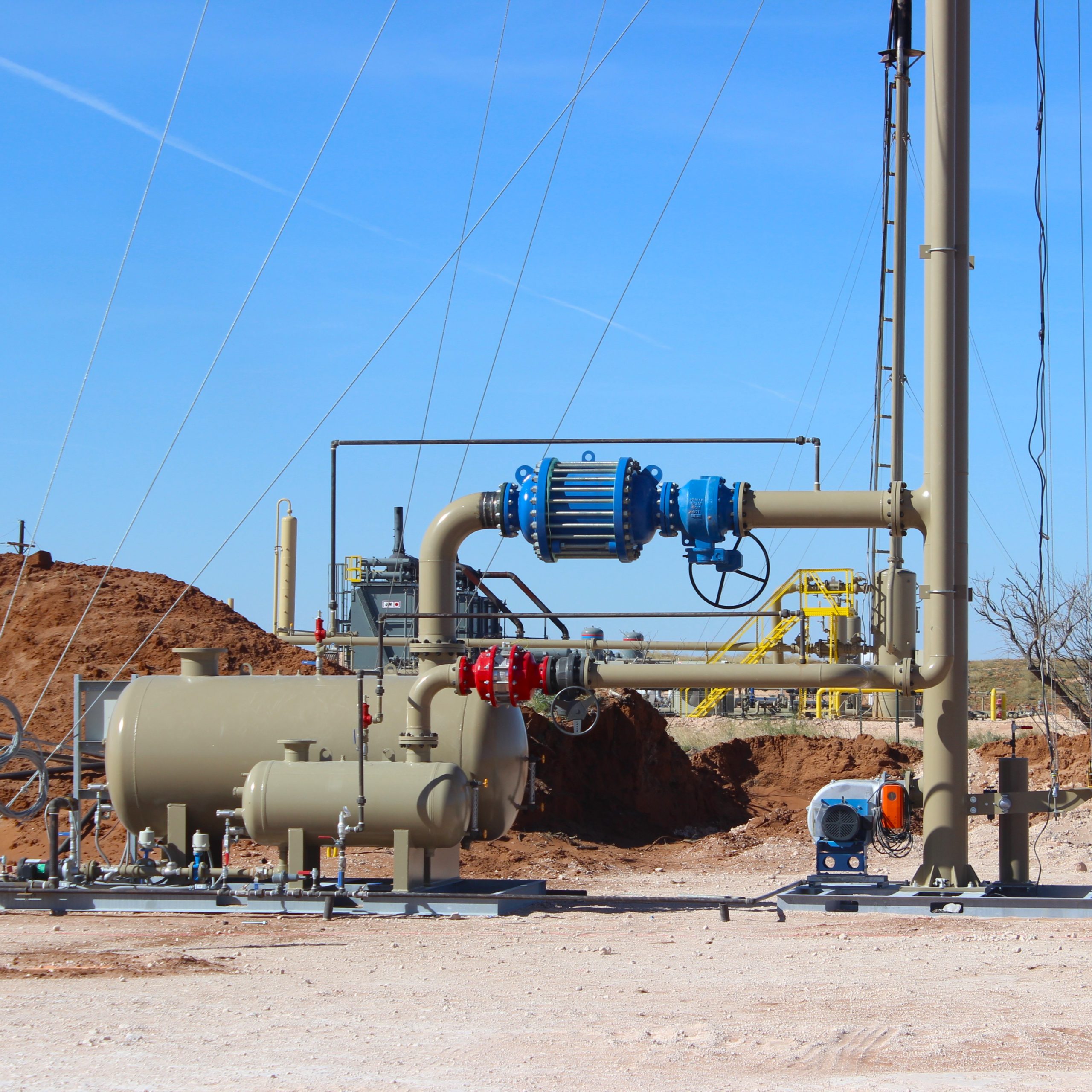
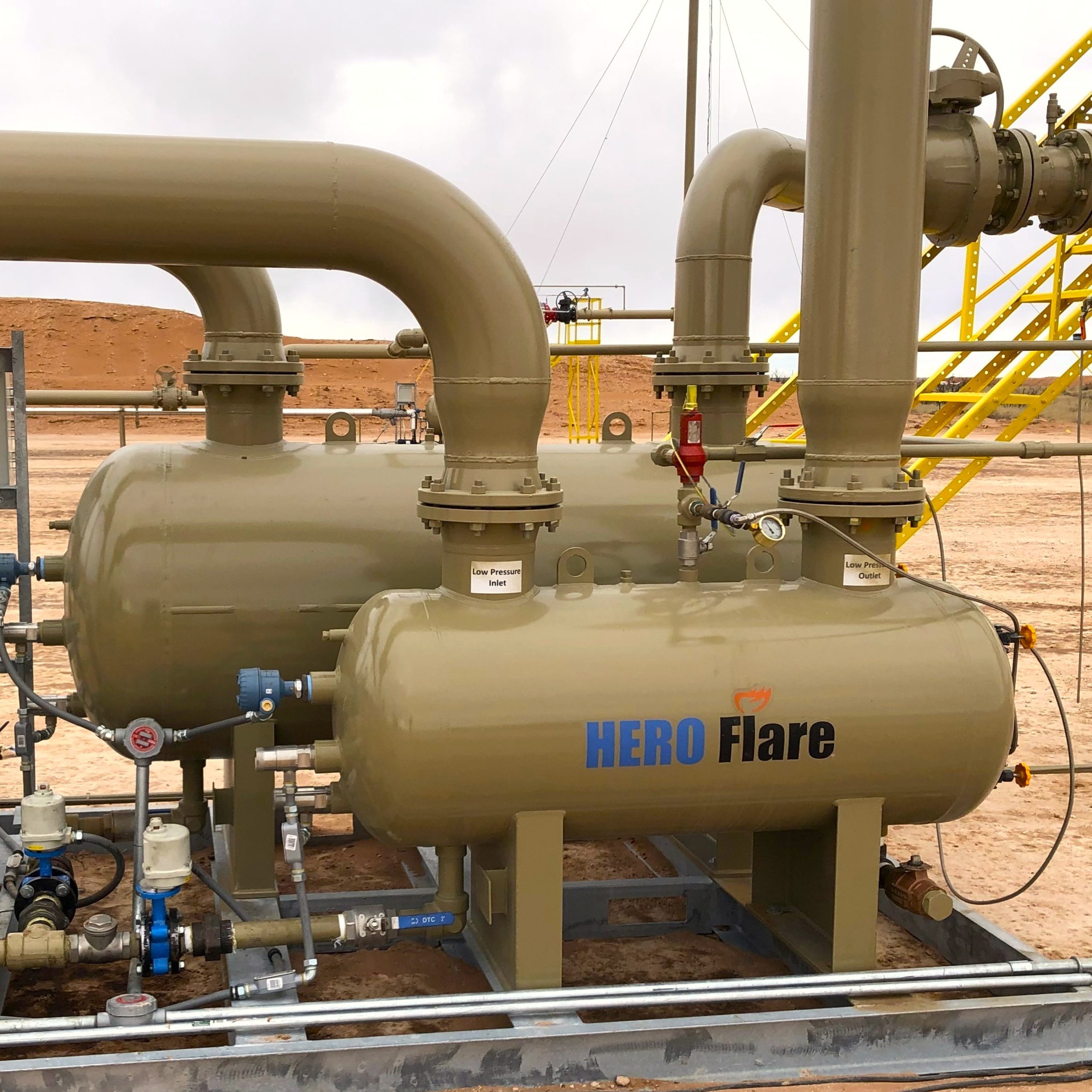
Liquid knockout systems — also called KO drums, knockout pots, or flare knockout drums — are pressure vessels that remove entrained liquid droplets from flare gas streams by reducing vapor velocity below the terminal settling velocity of target-size droplets. Per API Standard 521, Para. 5.4.2, knockout drums must be sized to separate droplets in the 300-to-600-micron range and provide 20-to-30 minutes of emergency liquid holdup capacity from the single largest relief contingency. Hero Process Solutions fabricates liquid knockout systems to ASME Section VIII Div. 1 at its Kellyville, OK manufacturing facility, in two-phase and three-phase configurations, horizontal and vertical orientations.

Liquid knockout systems are pressure vessels installed upstream of the flare stack that strip entrained liquid droplets from the relief gas stream before combustion occurs. Without a properly sized knockout drum in your flare header network, liquid hydrocarbon droplets reach the flare tip, fall as burning rain, and create a ground-level fire hazard that OSHA and EPA regulations treat as a process safety failure.

Hero Process Solutions designs and fabricates liquid knockout systems from its manufacturing facility in Kellyville, Oklahoma, with field operations supporting installation and commissioning across the Permian Basin, Midcontinent, and Gulf Coast. The product line spans two-phase and three-phase configurations in horizontal and vertical orientations, engineered to customer-specific flow rates and relief scenarios. Founded in 2011 and formerly operating as Hero Flare, the company delivers custom-engineered combustion and process equipment globally.

1. What Is a Liquid Knockout System and Why Your Flare Header Needs One

A liquid knockout system serves one core function: keep liquid out of the flare tip. Every industrial flare header collects relief gas from multiple pressure safety valves (PSVs), emergency blowdowns, and process upsets. That gas routinely carries liquid droplets. Some arrive as liquid slugs released directly from process vessels. Others form during transit as gas cools and hydrocarbons condense inside the header piping.

If those droplets reach the flare burner tip, combustion is incomplete. Unvaporized droplets exit the flame envelope, ignite in mid-air, and fall to grade. That phenomenon — known as burning rain — can reach adjacent equipment, personnel areas, and secondary containment zones. It is a documented failure mode with multiple incident records in upstream and midstream operations. The liquid knockout system stops burning rain at the source: by dramatically reducing gas velocity inside the vessel, the drum allows gravity to pull liquid droplets downward into the sump while dry gas continues to the flare stack.

Where Liquid Knockout Systems Sit in the Flare Network

  • Installed on the main flare header, upstream of the flare stack and any liquid seal drum
  • Located no more than 100 meters from the flare stack to minimize re-condensation downstream
  • Slope-drained from the header at 21 mm per 10 meters (0.25 in/10 ft) toward the drum per API 521
  • Can be supplemented by satellite KO vessels inside battery limits for sources with high liquid release rates
  • Also installed upstream of compressor suction to prevent liquid slugs from damaging impellers and valve plates

When a liquid source upstream releases large volumes intermittently — such as during a vessel blowdown or PSV lift event — the knockout drum must absorb that surge without allowing the liquid level to exceed the high-high alarm (LAHH) and compromise vapor-liquid disengagement. Liquid knockout systems that are correctly sized for this worst-case scenario prevent both burning rain at the flare and liquid carryover into compressor suction piping.

2. Two-Phase vs. Three-Phase Liquid Knockout Systems: Selecting the Right Configuration

Liquid knockout systems are classified by how many fluid phases they must separate. Choosing the wrong configuration is a design error that no amount of operational adjustment can correct after the vessel ships.

Two-phase knockout drums separate vapor from total liquid. This is the baseline design for most upstream flare header applications where the liquid fraction is predominantly condensate and the goal is simply to prevent liquid carryover to the flare tip. Two-phase liquid knockout systems are simpler, lower-cost, and appropriate when no free water is expected in the relief stream.

Three-phase knockout drums separate vapor, liquid hydrocarbons, and produced water simultaneously. Three-phase designs are required when water injection, steam tracing, or aquifer breakthrough creates a water phase in the relief stream. They require an additional water outlet nozzle, interface level control, and internal baffling. Free water at the flare tip creates steam explosions that mechanically damage the burner assembly — a failure mode distinct from burning rain but equally hazardous.

Configuration Phase Separation Best Applications Key Advantage
Two-Phase KO Drum Gas + total liquid Upstream production, gas processing, pipeline headers Simpler design, lower fabrication cost
Three-Phase KO Drum Gas + oil + water Water injection facilities, steam-assisted recovery, offshore Prevents steam explosion at flare tip from free water
Vertical KO Drum Gas + liquid (low flow) Compact sites, base-of-stack integration, low liquid load Minimal plot footprint
Horizontal KO Drum Gas + liquid (high flow) Refineries, large gathering systems, high-flow relief headers Large disengagement area; handles liquid slugs without re-entrainment

Key Insight

Three-phase liquid knockout systems are required at any facility where produced water can enter the flare header. Free water at the flare tip creates steam explosions that mechanically damage the burner assembly and pilot flame system — an equipment failure that can take the flare offline during an active emergency relief event.

3. Horizontal vs. Vertical Knockout Drum Orientation: Engineering the Right Choice

The choice between horizontal and vertical orientation follows directly from vapor flow rate, available plot space, and expected liquid load. It is not a preference decision — it is an engineering calculation.

Horizontal Knockout Drums

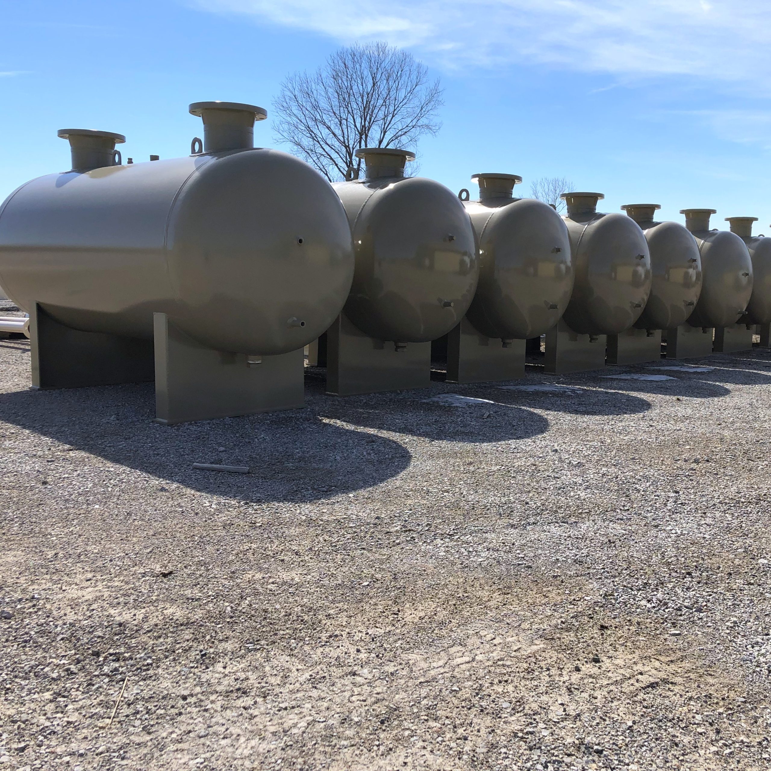
Horizontal liquid knockout systems are the standard for large-scale refinery and midstream applications. The orientation provides a large vapor-liquid disengagement area and handles high liquid slug events without re-entraining already-settled droplets into the outlet gas. Horizontal vessels maintain low pressure drop across the drum, which is critical in flare header systems where backpressure must stay within PSV set pressure calculation limits. Three common flow path configurations exist:

  • Gas enters one end axially, exits at the top of the opposite end
  • Gas enters each end on the horizontal axis with a central vapor outlet
  • Gas enters at the center and exits at each end horizontally

The length-to-diameter ratio (L/D) for horizontal liquid knockout systems typically runs 2:1 to 4:1. This range maintains vapor velocity low enough for gravitational droplet separation without requiring an impractically long vessel. L/D outside this range indicates a resizing is needed, not a ratio adjustment.

Vertical Knockout Drums

Vertical knockout drums work best when liquid loads are low and plot space is the binding constraint. They are commonly incorporated into the base of the flare stack itself, eliminating the need for a separate horizontal vessel and interconnecting header piping. Vertical drums are sensitive to liquid slug events — upward vapor velocity can re-entrain liquid that has already settled to the sump — making them unsuitable for sources with intermittent large liquid releases.

A minimum of 600 to 900 mm of free vapor space above the LAHH is required in any orientation to prevent surface disturbance from re-entraining droplets into the vapor outlet during high-flow surge events.

4. API 521 Sizing Requirements for Liquid Knockout Systems

API Standard 521, “Pressure-relieving and Depressuring Systems,” Para. 5.4.2 is the governing document for knockout drum sizing. The methodology follows two sequential steps, and both must be satisfied before a vessel size is finalized.

Step 1: Vapor-Liquid Disengagement Sizing

The drum diameter must be large enough that vapor velocity falls below the terminal settling velocity of the target droplet size. API 521 sets the target droplet at 300 to 600 microns. Droplets larger than 600 microns represent a burning rain risk; droplets below 300 microns are typically consumed in the flare flame without reaching grade. Terminal settling velocity is calculated using the Souders-Brown equation with a K-factor ranging from 0.15 to 0.35 for KO drum applications — lower values for mist-heavy streams, higher values for vapor-dominant flows. Engineers calculate maximum allowable velocity, then back-calculate the required cross-sectional area and drum diameter.

Step 2: Liquid Holdup Volume Sizing

The drum must store the liquid volume from the single largest emergency relief contingency for 20 to 30 minutes. This window represents the time operators need to stabilize the plant, reduce inlet flow, or initiate an emergency shutdown before the drum reaches its LAHH trip point. When the expected emergency liquid volume exceeds 30 minutes of holdup at the initially sized diameter, the vessel length is extended — not the diameter, which is already set by vapor velocity requirements.

Critical Rule

API 521 Para. 5.4.2 requires a minimum of 20-to-30 minutes of liquid holdup based on the largest single relief contingency — not average flow. Size for the worst credible case: typically a total plant power failure or fire case relief scenario. Undersizing holdup volume is the most common root cause of burning rain incidents in brownfield operations.

Inlet Deflector Requirements

High-velocity relief streams entering the knockout drum carry significant kinetic energy. An impingement plate or Schoepentoeter inlet device at the nozzle is required to break up the gas stream before it enters the disengagement zone. Without proper inlet energy dissipation, the entering jet atomizes partially separated liquid back into fine mist — smaller than 300 microns — effectively defeating the sizing calculation entirely.

5. ASME Section VIII Fabrication Standards for Knockout Drums

Liquid knockout systems are pressure vessels subject to ASME Boiler and Pressure Vessel Code Section VIII Division 1. Even when a formal ASME stamp is not contractually required, the standard governs wall thickness calculations, material selection, weld joint efficiency factors, and nozzle reinforcement design.

Typical Construction Materials

  • Carbon steel ASTM A516 Grade 70 — standard for ambient to moderate temperature service; most upstream and midstream knockout drum applications
  • ASTM A333 Grade 6 — for low-temperature carbon steel (LTCS) service down to -50°F (-46°C); arctic installations or cryogenic relief streams
  • Stainless steel 304L or 316L — where sour service or high-chloride produced water requires corrosion-resistant alloy
  • ASTM A105 forgings — nozzles and flanges in standard carbon steel pressure classes

ASME Stamp and Inspection

The ASME U-stamp is required when the vessel is subject to jurisdictional inspection requirements, which applies in most US states and Canadian provinces for vessels meeting pressure and volume thresholds. Hero Process Solutions fabricates with ASME U-stamp capability and maintains National Board registration for vessels requiring formal third-party inspection.

Ongoing in-service inspection falls under API Standard 510, “Pressure Vessel Inspection Code,” which specifies inspection intervals based on corrosion rate measurements from previous inspection cycles. Knockout drums are classified as dirty service — internal corrosion from acidic condensates and H2S-bearing streams requires scheduled gauge glass cleaning, level instrument verification, and internal inspection access.

6. Integration with Flare Systems and 3-Phase Separators

Liquid knockout systems do not operate in isolation. In upstream production facilities, the flare header network connects directly to the output of 3-phase separators and other process vessels. Understanding what is upstream of the KO drum — and what emergency liquid loads each source can generate — is essential for correct knockout drum sizing.

When a 3-phase separator overflows or bypasses liquid during a plant emergency, that liquid enters the flare header. The KO drum must be sized to handle that surge volume, not just steady-state condensation from the gas stream. When the 3-phase separator is already handling large continuous liquid loads, a satellite KO vessel installed inside the battery limit upstream of the main drum removes bulk liquid from the header — reducing the main drum’s sizing burden and improving product recovery efficiency.

Key Insight

The liquid seal drum and the knockout drum serve completely different functions and must not be confused in system design. The liquid seal drum prevents flashback from the flare tip back down the header. The knockout drum prevents liquid from reaching the flare tip in the first place. A complete flare system requires both, and neither substitutes for the other.

Knockout Drums Upstream of Compressor Suction

When gas is recovered from the flare header for compression and reuse, a separate KO drum upstream of the compressor suction protects the compressor from liquid slugs that would mechanically damage impellers or valve plates. This vessel is distinct from the flare header KO drum and is sized for continuous-flow conditions rather than emergency relief. Hero Process Solutions sizes and fabricates both types of liquid knockout systems from the same facility.

7. Manual Dump vs. Automated Liquid Level Control

Once liquid accumulates in the knockout drum sump, it must be removed continuously or on demand. The two approaches differ in response speed, risk tolerance, and applicability.

Manual dump systems use a manually operated valve at the drum sump outlet. An operator monitors the level gauge glass or level indicator and opens the valve to drain collected liquid to a skim tank, produced water handling system, or slop line. Manual systems suit low-liquid-load applications where accumulation rates are slow and the facility is continuously staffed. They should never be specified as the only drainage path at facilities where the expected liquid filling rate during an emergency could reach LAHH within 30 minutes.

Automated liquid level control systems use a level transmitter, controller, and motor-operated or pneumatic valve to drain the drum automatically when the liquid level reaches a set point. Automated systems are required for high-liquid-load applications, remote or minimally staffed facilities, and any installation where the expected emergency filling rate would reach LAHH before an operator could physically respond.

Critical Rule

OSHA Process Safety Management (PSM) assessments under 29 CFR 1910.119 routinely identify manual-only dump systems as a risk-reduction opportunity in high liquid-load flare systems. Automated dump with high-level alarm and automatic high-high level shutdown to upstream relief sources is the recognized engineering best practice for any facility subject to PSM requirements.

8. EPA Compliance and Regulatory Standards for Liquid Knockout Systems

Liquid knockout systems are not directly listed as a regulated control device under EPA 40 CFR 60 Subpart OOOOb — but they are integral to the performance of the flare systems that are. A flare cannot maintain 98%+ combustion efficiency if liquid carryover is occurring, because liquid hydrocarbons entering the flame cause incomplete combustion and visible smoke.

Connection to Subpart OOOOb Flare Compliance

  • EPA 40 CFR 60 Subpart OOOOb mandates combustion efficiency monitoring and reporting for flares used to comply with methane and VOC emission limits
  • Liquid carryover events increase visible emissions and reduce measured combustion efficiency
  • Continuous parameter monitoring systems (CPMS) and regulatory inspectors can identify degraded flare performance that traces to inadequate knockout drum sizing
  • A properly sized liquid knockout system is a prerequisite for sustained Subpart OOOOb flare compliance, not a separate regulatory requirement

For additional guidance on EPA 40 CFR 60 Subpart OOOOb compliance for your facility’s flare system, review Hero Process Solutions’ OOOOb compliance resources.

Applicable Standards Summary

Standard Organization Application to KO Drums
API Standard 521, Para. 5.4.2 American Petroleum Institute Primary sizing standard — droplet separation and holdup volume
API Standard 537 American Petroleum Institute Flare details and KOD integration requirements
API Standard 510 American Petroleum Institute In-service pressure vessel inspection intervals
ASME BPVC Section VIII Div. 1 ASME Pressure vessel design and fabrication standard
API RP 14J American Petroleum Institute Offshore flare system design with KOD requirements (400-500 micron target)
EPA 40 CFR 60 Subpart OOOOb US EPA Flare combustion efficiency requirements (indirectly tied to KOD performance)

9. Hero Process Solutions Liquid Knockout Systems: Engineering and Manufacturing Options

Hero Process Solutions manufactures liquid knockout systems at its Kellyville, Oklahoma facility, with engineering and field services support from its Midland, Texas operations. Every knockout drum is engineered to the customer’s specific relief scenario — there are no catalog sizes for flare KO drums because relief loads, fluid properties, and holdup requirements vary by site.

Vessel Configurations

  • Two-phase or three-phase separation
  • Horizontal or vertical orientation
  • Axial, side, or tangential inlet
  • Full vacuum to high-pressure MAWP ratings

Level Instrumentation

  • Magnetic or reflex gauge glass
  • Displacer or guided-wave radar transmitters
  • HL and HHL alarm switches
  • Automated dump valve packages

Materials and Certification

  • Carbon steel (standard), LTCS, SS, clad
  • ASME U-stamp fabrication
  • National Board registration
  • Third-party inspection available

Hero Process Solutions also provides field services for commissioning, inspection, and maintenance of liquid knockout systems already in service. Contact the engineering team at sales@hero-ps.com or (918) 941-2166 to discuss your application.

Common Mistakes in Liquid Knockout System Design and Operation

Mistake Why It Hurts Operations Fix
Sizing holdup for average liquid flow rather than peak emergency case LAHH trip reached within minutes during full plant blowdown; burning rain occurs before operators can respond Size for the single largest contingency at maximum relief load per API 521
Specifying vertical drum when liquid loads are high or slug-type High upward vapor velocity re-entrains settled liquid; effective separation is never achieved Use horizontal orientation for high liquid load or intermittent slug releases
Omitting an inlet deflector or impingement plate Inlet jet atomizes liquid into sub-300-micron mist that gravity cannot settle; carryover to flare tip Specify impingement plate or Schoepentoeter at all inlet nozzles
Insufficient vapor space above LAHH During gas surge events, liquid surface disturbance entrains droplets into vapor outlet nozzle Maintain minimum 600 to 900 mm of free vapor space between LAHH and vapor outlet
Locating KO drum more than 100 m from flare stack Re-condensation in the downstream header defeats the separation effort; liquid reaches the flare tip Position knockout drum within 60 to 100 meters of the flare stack
Using manual dump only on high-liquid-load applications Operator cannot drain sump fast enough during emergency relief; drum fills to LAHH and liquid carries over Install automated level control with high-high level shutdown for high-liquid-load service

Article Summary

Key Takeaways: Liquid Knockout Systems

  • Liquid knockout systems remove entrained liquid droplets from flare relief gas streams before combustion, preventing the burning rain failure mode
  • API Standard 521, Para. 5.4.2 governs KO drum sizing, targeting droplets in the 300-to-600-micron range using the Souders-Brown equation with K-factors of 0.15 to 0.35
  • Emergency liquid holdup volume must cover 20 to 30 minutes of relief at the single largest contingency flow rate — not average flow
  • Horizontal knockout drums are preferred for high vapor flow and high liquid load; vertical drums suit compact spaces and low liquid-rate applications
  • Length-to-diameter ratios of 2:1 to 4:1 for horizontal vessels maintain vapor velocity below droplet terminal settling velocity
  • Three-phase liquid knockout systems are required where produced water can enter the flare header
  • ASME Section VIII Div. 1 governs fabrication; API Standard 510 governs in-service inspection intervals
  • Inlet deflectors at the inlet nozzle are required to prevent jet atomization from defeating the droplet separation calculation
  • Automated liquid level control is the engineering best practice for high-liquid-load and remote applications per OSHA PSM guidance
  • EPA 40 CFR 60 Subpart OOOOb combustion efficiency compliance is directly tied to adequate liquid knockout drum sizing — liquid carryover to the flare tip degrades measurable combustion efficiency and can constitute a permit deviation

Frequently Asked Questions

What is a liquid knockout system in oil and gas? +
A liquid knockout system is a pressure vessel installed in the flare header network upstream of the flare stack. It removes liquid droplets from the relief gas stream by reducing vapor velocity below the terminal settling velocity of target-size particles — typically 300 to 600 microns per API Standard 521. Without an adequately sized knockout drum, liquid droplets reach the flare burner, causing incomplete combustion, visible smoke, and the burning rain hazard where partially burning liquid falls to grade.
How is a knockout drum sized per API 521? +
Knockout drum sizing follows API Standard 521, Para. 5.4.2, in two steps. Step 1 determines the drum diameter needed to keep vapor velocity below the terminal settling velocity of a 300-to-600-micron droplet, using the Souders-Brown equation with a K-factor of 0.15 to 0.35 depending on service conditions. Step 2 sizes the liquid holdup volume to store the largest emergency relief liquid load for 20 to 30 minutes. Whichever requirement yields the larger vessel dimension governs the final design. Engineers use trial-and-error iteration between diameter and length, constrained by the L/D ratio of 2:1 to 4:1 for horizontal drums.
What is the difference between horizontal and vertical knockout drums? +
Horizontal knockout drums provide a larger vapor-liquid disengagement area and handle high vapor flow rates and liquid slug events without re-entraining settled liquid. They are the standard for refinery and large gathering system applications. Vertical knockout drums occupy less plot space and suit low-liquid-load applications, often installed at the base of the flare stack itself. Horizontal orientation is preferred whenever vapor flow is high, liquid loads are significant, or slug-type releases are expected from upstream separators or blowdown systems.
What causes burning rain at a flare stack? +
Burning rain occurs when liquid hydrocarbon droplets bypass the knockout drum and enter the flare flame envelope. Droplets that do not fully vaporize and combust within the flame exit as partially burning liquid that falls to grade. It results from inadequate knockout drum sizing, drum level exceeding LAHH during emergency relief releases, or missing inlet deflectors that allow the entering jet to atomize liquid back into fine mist. Proper API 521-compliant knockout drum sizing — with correct holdup volume for the worst-case contingency — is the primary engineering control.
Does a liquid knockout drum require an ASME U-stamp? +
Most US states and Canadian provinces require ASME Section VIII Div. 1 certification and a U-stamp for pressure vessels above minimum pressure and volume thresholds. Hero Process Solutions fabricates liquid knockout systems with ASME U-stamp capability and National Board registration. Even where formal stamping is not jurisdictionally required, designing and building to ASME VIII provides the documented quality basis required for PSV set pressure calculations, management of change (MOC) records, and jurisdictional inspection programs under API Standard 510.
How do liquid knockout systems affect EPA Subpart OOOOb flare compliance? +
EPA 40 CFR 60 Subpart OOOOb requires flares used to control regulated sources to achieve 98%+ combustion efficiency and comply with specific operating parameter limits under continuous parameter monitoring. Liquid carryover from an undersized or overloaded knockout drum reduces flare tip combustion efficiency and generates visible smoke — both of which can constitute a permit deviation reportable to the EPA and the applicable state agency. A properly sized liquid knockout system is a design prerequisite for sustained Subpart OOOOb flare compliance, not a separate requirement.
Custom-Engineered for Your Application

Ready to Size Your Liquid Knockout System?

Send us your flare header flow rates, operating pressure, expected liquid load, and emergency relief scenario. Our engineering team will return a recommended vessel configuration with API 521 sizing basis.

Request a Free Sizing Review (918) 941-2166  ·  Talk to an Engineer